![1 generation [2007 - 2012]](/uploads/peugeot-4007-suv-news-reports_9.jpg)

Tools:
- Ratchet wrench
- Extension (with cardan)
- Head 10 mm
- Head 12 mm
- Head 14 mm
- Head 18 mm
- Open end wrench 10 mm
- Straight ring wrench 12 mm
- Straight ring wrench 14 mm
- 16 mm bent box wrench
- 6mm hex wrench
- torque wrench
- Screwdriver flat medium
- Phillips screwdriver, medium
- screw jack
- lifting device
- Traverse MB991527
- balloon wrench
- Hex wrench for fixing the tensioner (or pin)
- Pliers
- Marker
- Wheel chock (shoe)
- Knife (or scraper)
- Syringe for technical fluids
- Funnel
Parts and consumables:
- Bracket MB991956
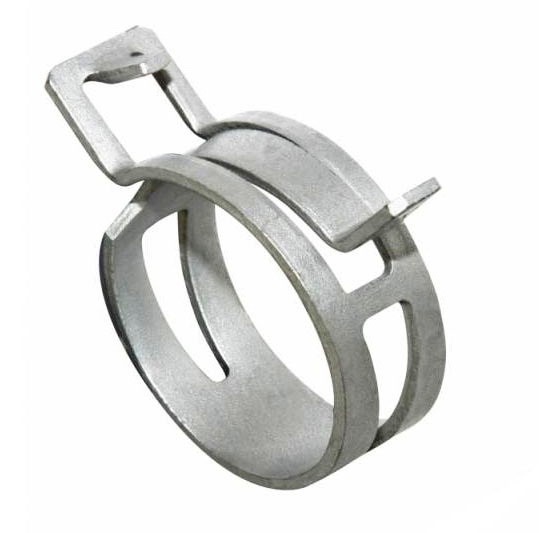
- Radiator hose clamp MR993229 (models from 03.2009) - 2 pcs.
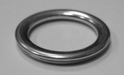
- O-ring for engine sump plug 0313.41

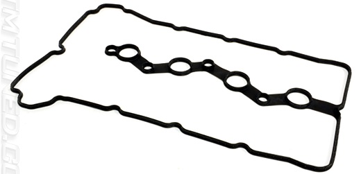
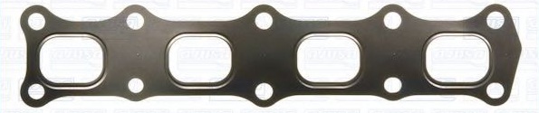
- Exhaust manifold gasket 0349.N1
- O-ring for downpipe and manifold 1712.C6 (if required)
- Downpipe seal 1709.42 (if required)
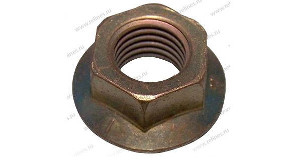
- Exhaust manifold fastening nut 0341.N4 - 5 pcs.
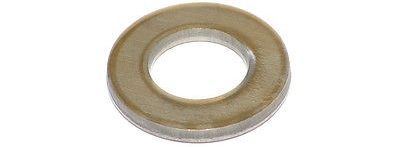
- Washer 0341.N3 - 5 pcs.
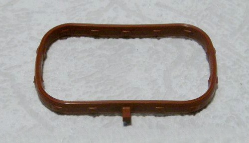
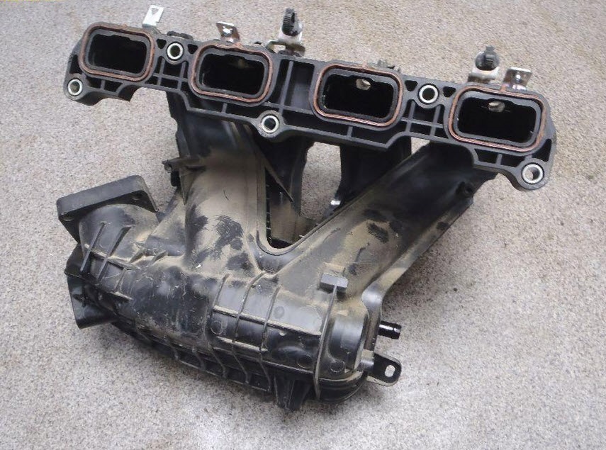
- Intake manifold gasket 0348.V1 - 4 pcs.
- Accessory drive belt 5750.YT (if required)
- Auxiliary drive belt tensioner 5751.G5 (if required)
- Motor oil
- Transmission oil
- Coolant
- Rope or wire
- Technical capacity - 4 pcs.
- Hose
- Aerosol lubricant type WD-40
- Cleaner (or solvent)
- wooden block
- rags
Notes:
This article shows you how to properly remove a 4B12 engine in case it needs to be replaced or overhauled.
When removing and installing the power unit, use only fully serviceable lifting mechanisms designed for the appropriate load, and especially carefully control the correctness and reliability of connecting cables, traverses, etc. to the transport eyes of the engine.
Removing the engine
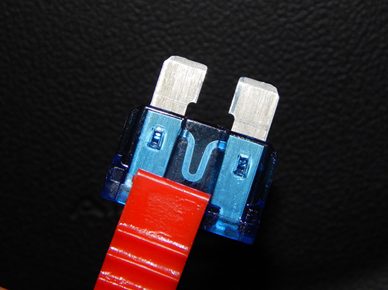
1. Reduce the pressure in the engine power system.
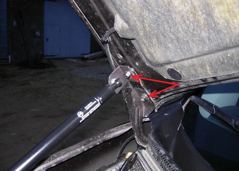
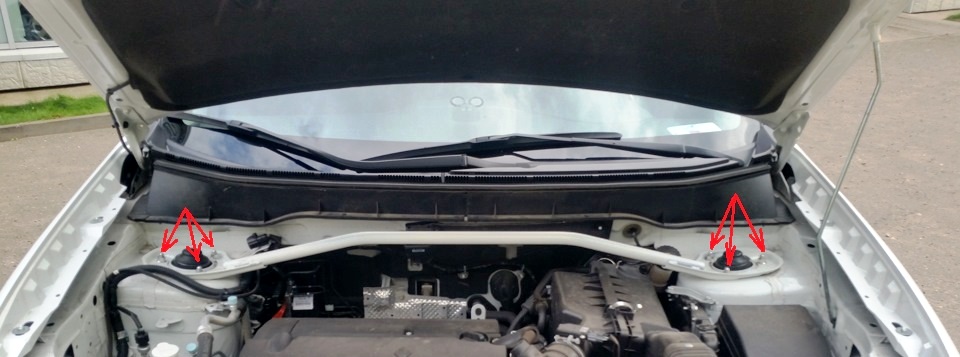
2. Remove the hood by unscrewing the nuts securing the brackets to the hood.
3. Remove engine mudguards (lower, front, rear and right side) as described here .

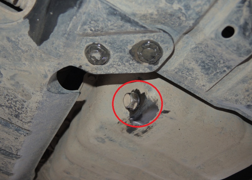
4. Remove the drain plug in the oil pan and drain the engine oil from the engine.
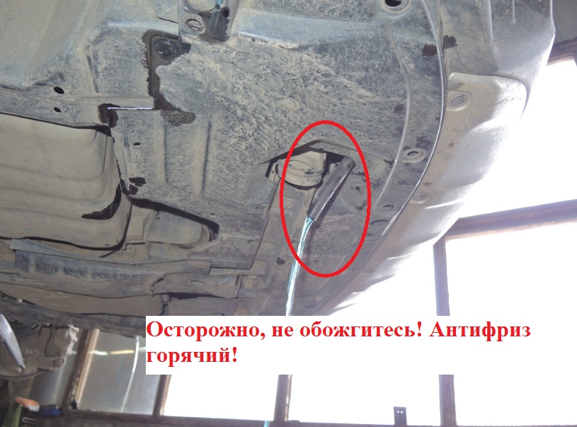
5. Drain the coolant by removing the drain plug on the radiator.
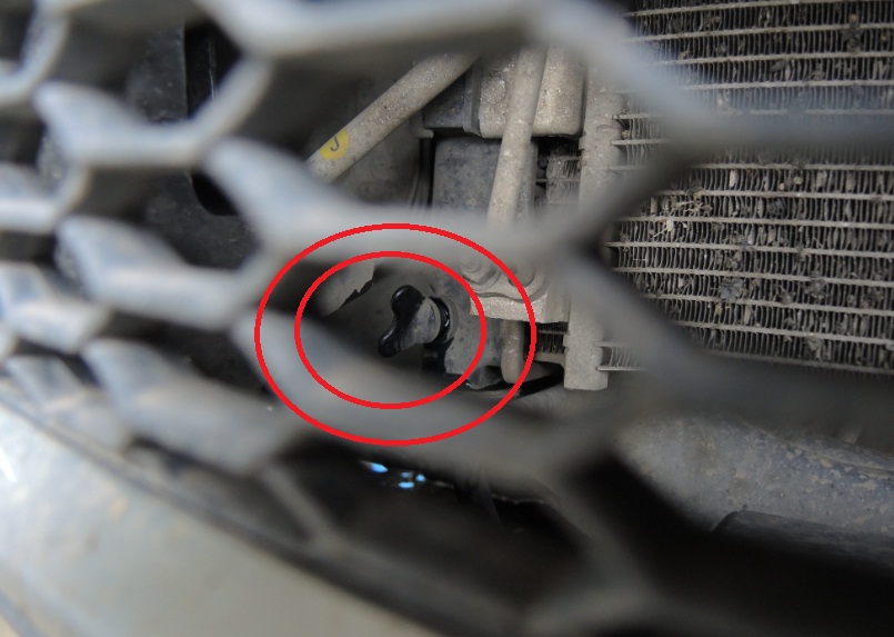
Note:
In order for the antifreeze to drain in a controlled manner into the prepared container, unscrew the drain plug and insert a hose into the drain hole, which, accordingly, immerse in the drain container.
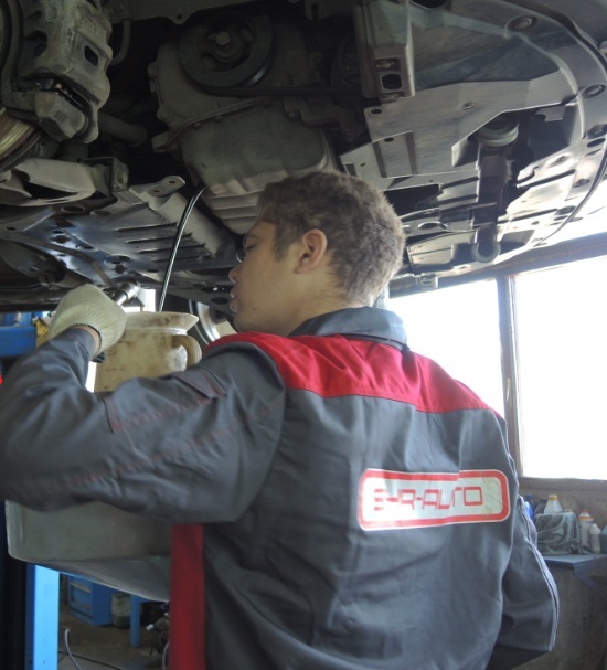
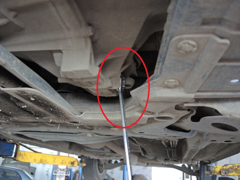
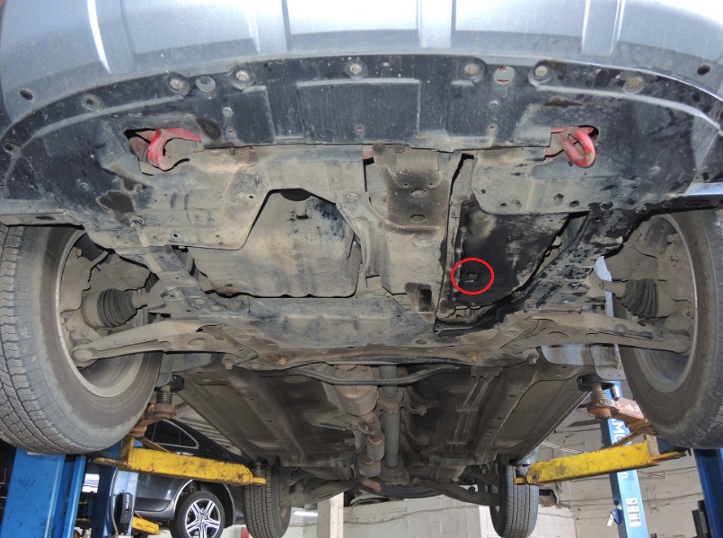
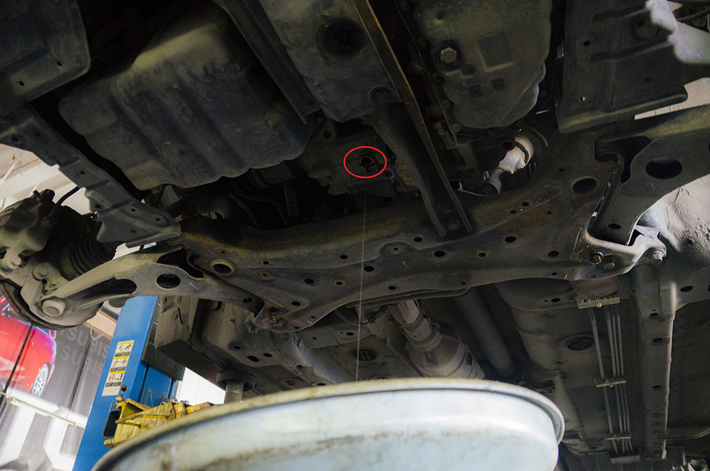
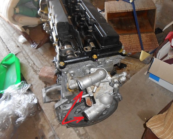
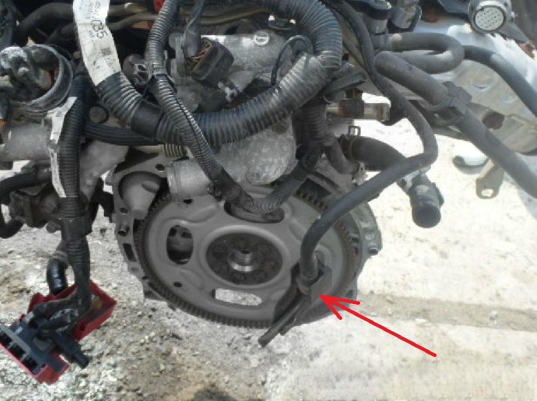
6. Drain the oil (manual transmission, see the first photo below) or the working fluid (variator) from the gearbox (see the second photo below), as well as the oil from the transfer case (4WD models, third photo below).
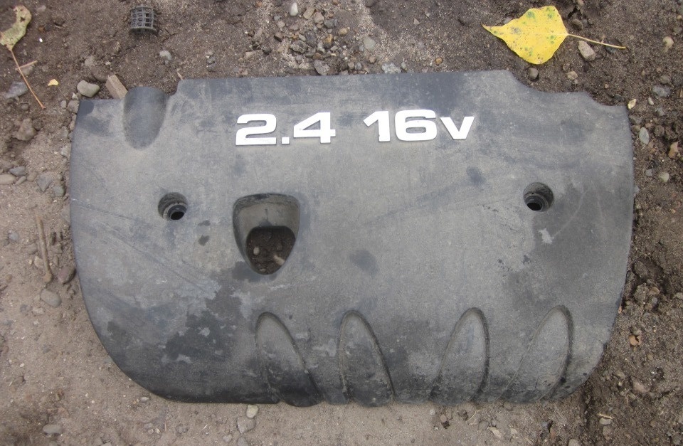
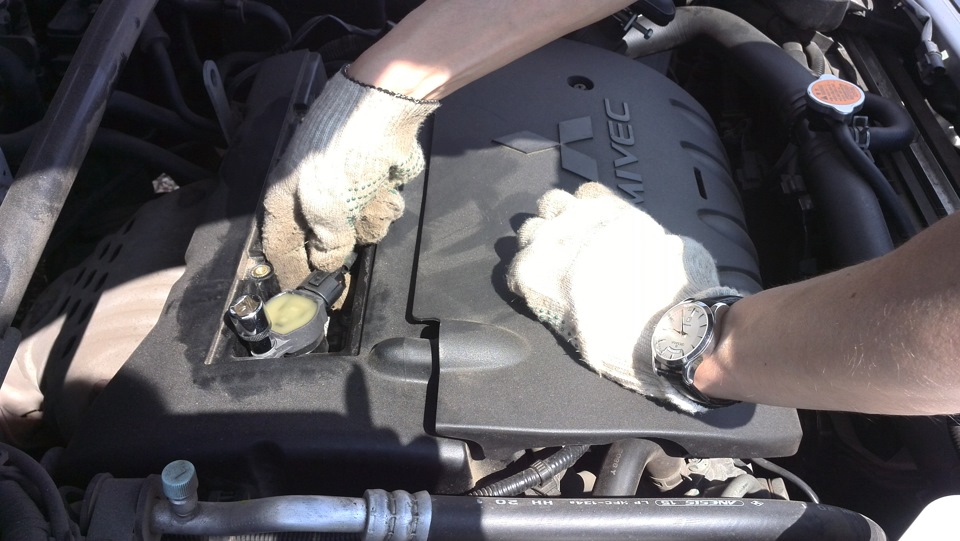
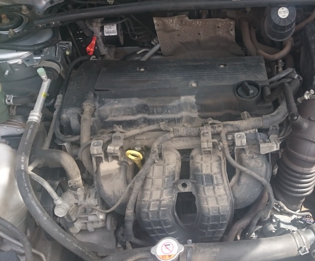
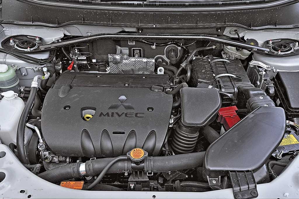
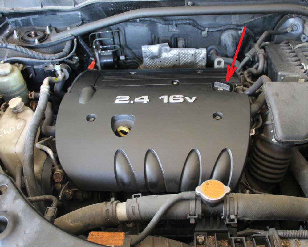
7. Remove the decorative engine cover as described here .
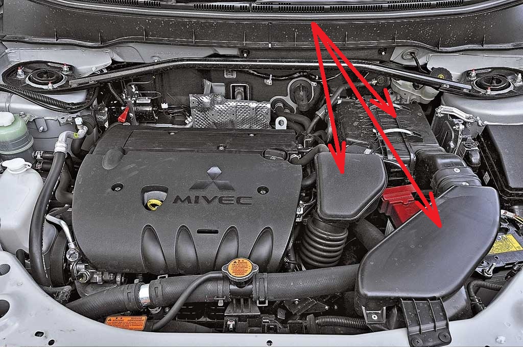
8. Remove the air filter assembly.
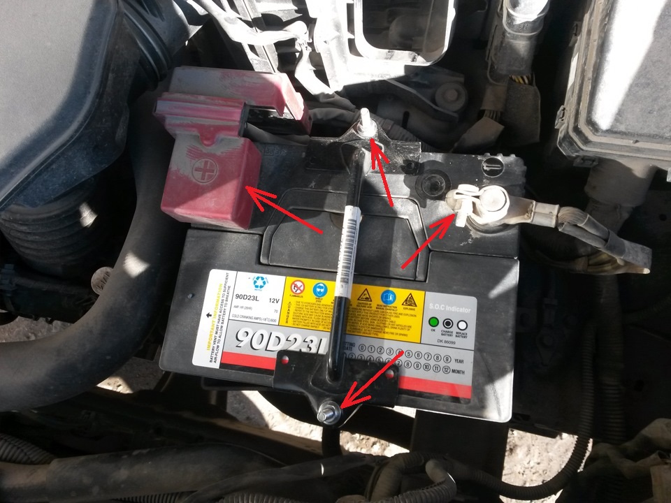
9. Remove the battery and battery tray.
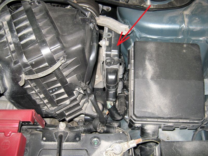
10. Remove the engine/engine and CVT electronic control unit.
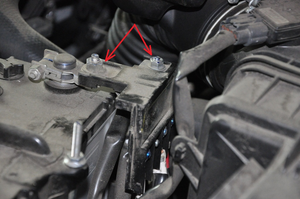
11. Remove the brace by unscrewing the six nuts with a spanner wrench.
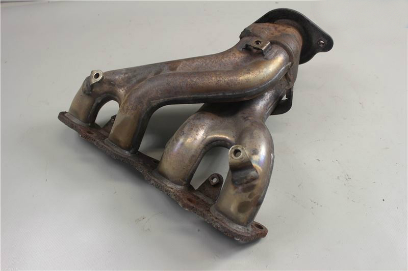
12. Remove the exhaust manifold as described here .
13. Disconnect the wire blocks from the ignition coils, as described in this article .
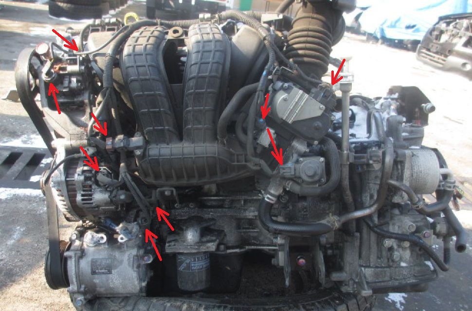
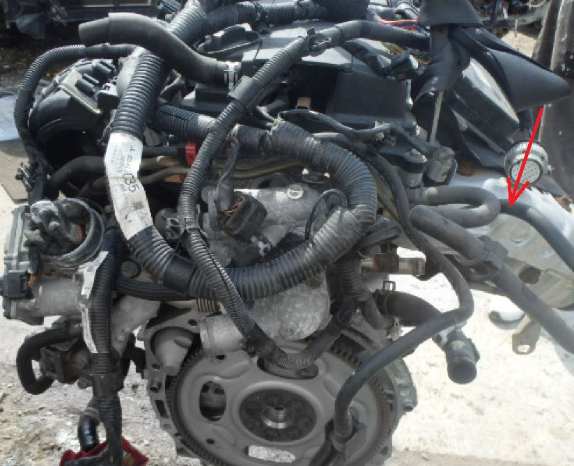
14. Disconnect the engine management system wiring harness from the sensors and power connectors to remove the engine management wiring harness connectors and clamps from the engine (for clarity, shown on the removed engine).
15. Turn away a nut of fastening of a wire of the storage battery and remove it.
16. Disconnect the top and bottom hoses of a radiator from branch pipes of the case of the thermostat.
16.1 (Models before 03.2009) After marking the relative position of the radiator hose and clamp, disconnect the radiator hose from the pipe on the engine.
Note:
After disconnecting the radiator hose, it is necessary to close the holes in the hose and pipe with plugs to prevent dust or foreign particles from entering them.
16.2 (models from 03.2009) Break off the teeth of the hose clamps and release the clamps, then disconnect the upper and lower radiator hoses from the thermostat housing.

Note:
If you do not break off the tooth of the hose clamp, then it will not be possible to open the clamp.
After disconnecting the radiator hose, it is necessary to close the holes in the hose and pipe with plugs to prevent dust or foreign particles from entering them.
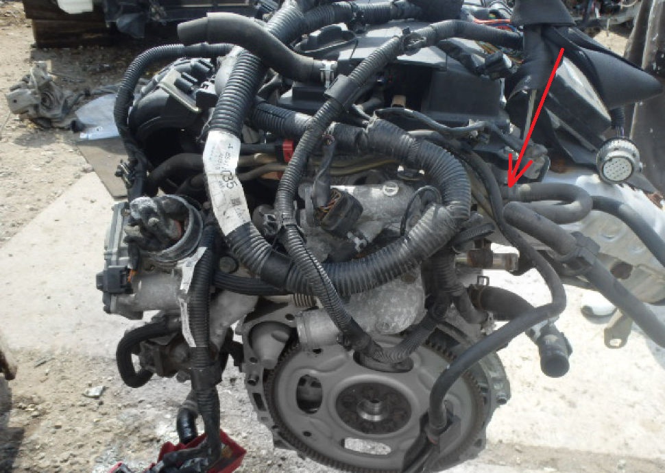
17. Then disconnect the heater hoses from the thermostat housing by first moving the clamps of their fastening (for clarity, it is shown on the removed engine).
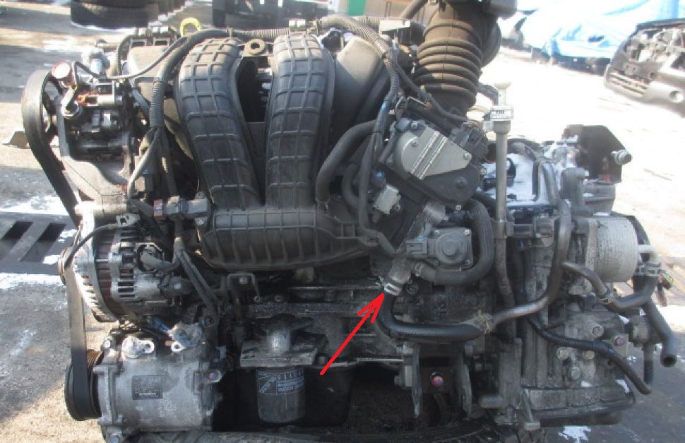
18. Separate a vacuum hose of system of catching of steams of fuel.
19. Separate a vacuum hose of the amplifier of brakes, having used pliers.
20. Using pliers, disconnect the coolant hose from the crankcase ventilation valve.
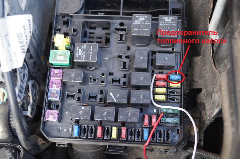
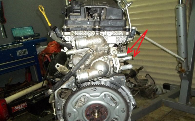
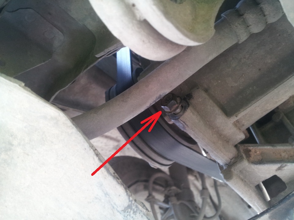
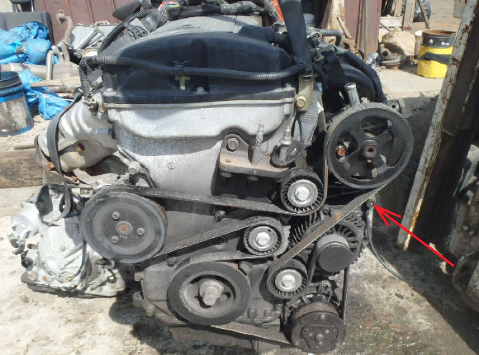
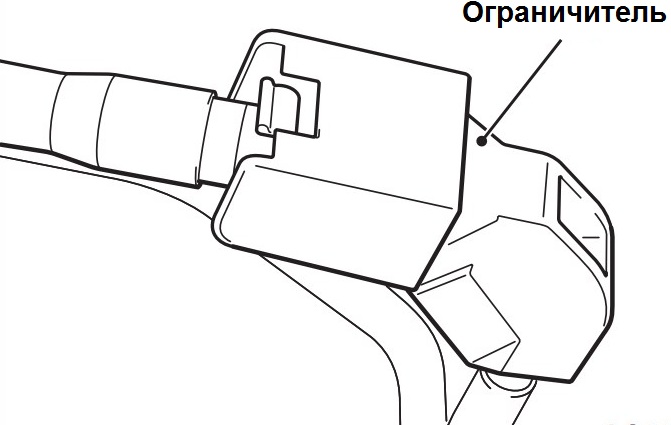
21. Remove the restrictor from the high pressure fuel hose.
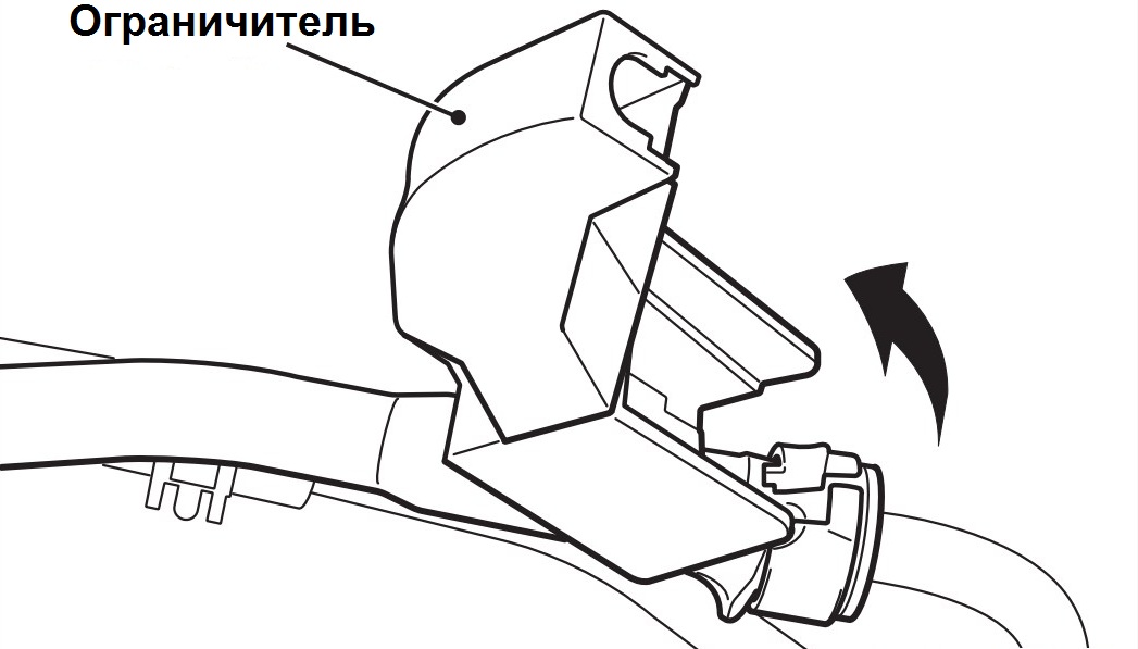
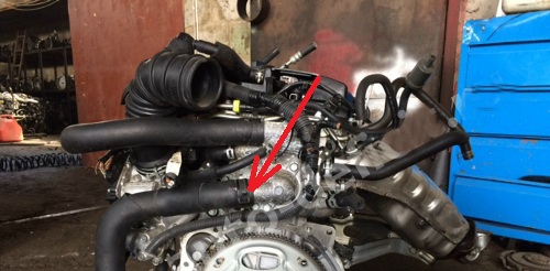
22. Release a clamp and pull a fuel hose in the direction specified by an arrow in drawing.
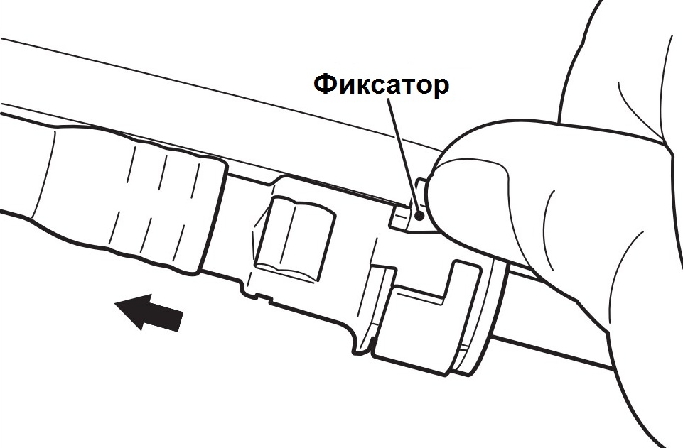
Note:
If the high pressure hose retainer has been released, reinstall it after disconnecting the hose.
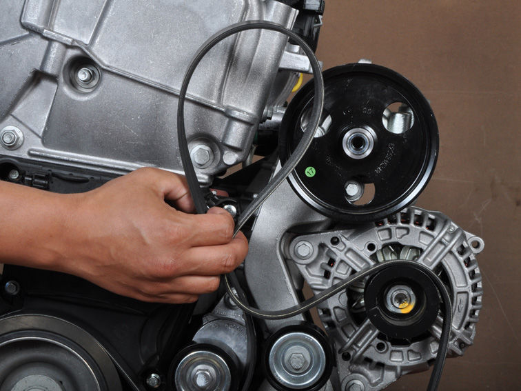
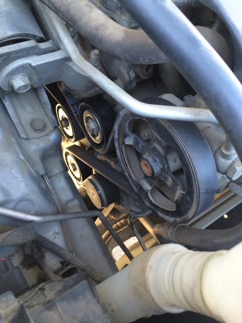
23. Remove the accessory drive belt as described here .
24. Remove the power steering pump assembly from the bracket along with the connected hoses.
Note:
Once removed, use wire or rope to hang the power steering pump assembly with hoses on the body in a location where they will not obstruct the removal and installation of the engine.
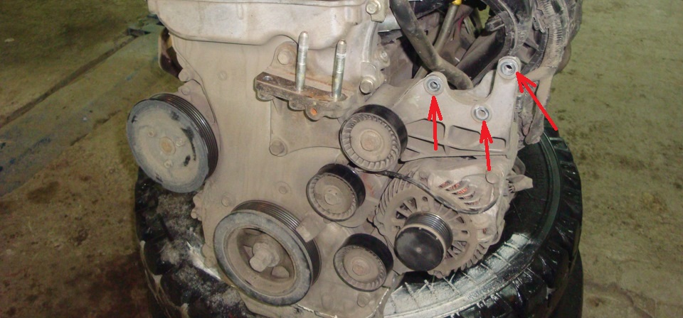
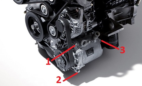
25. Loosen the mounting bolts of the air conditioning compressor and electromagnetic clutch assembly in the sequence shown in the figure.
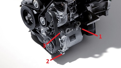
26. Remove the A/C compressor and magnetic clutch assembly from its bracket along with the hoses attached.
Note:
After removal, use a wire or rope to hang the air conditioning compressor assembly with hoses on the body in a place where they will not interfere with the removal and installation of the engine.
27. Remove intake manifold as described here .
28. Remove the gearbox / variator.

29. Turn away a bolt of fastening of a wire of "weight" to the generator.
30. Place a jack under the engine oil pan by inserting a block of wood between the jack foot and the engine oil pan.
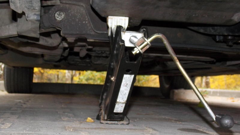
Note:
Be careful not to deform the oil pan when supporting the power package with a rolling jack.
31. Remove the special tools (engine lift) used to hang the engine when removing the gearbox.
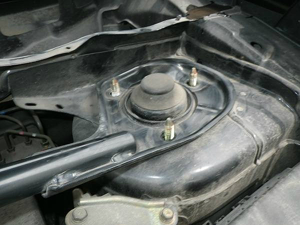
32. Using a jack, slightly raise the engine to unload the right support from the weight of the engine.
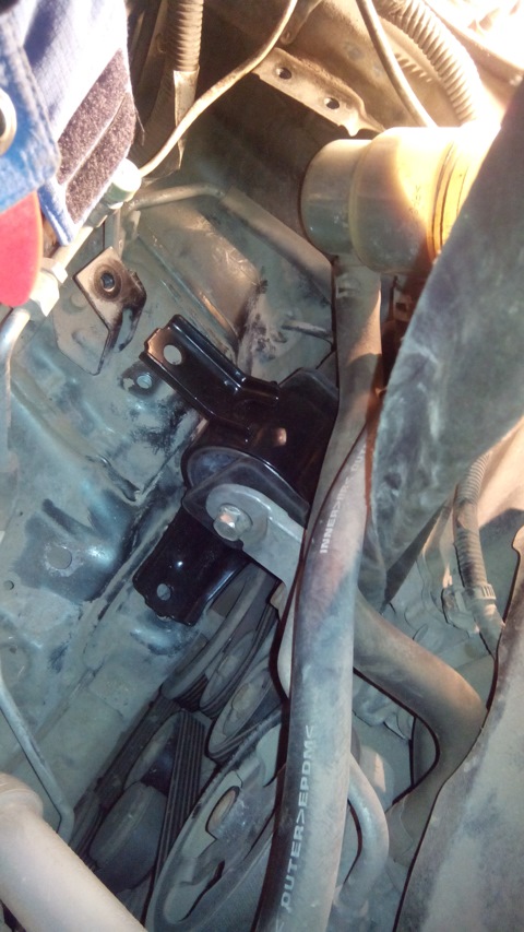
33. Turn away a nut and bolts of fastening, remove an engine support.
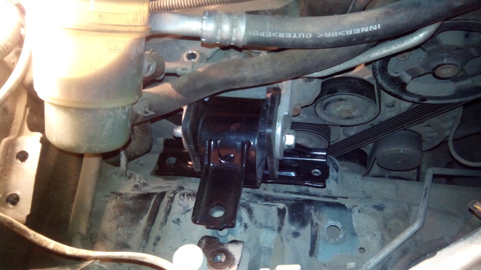
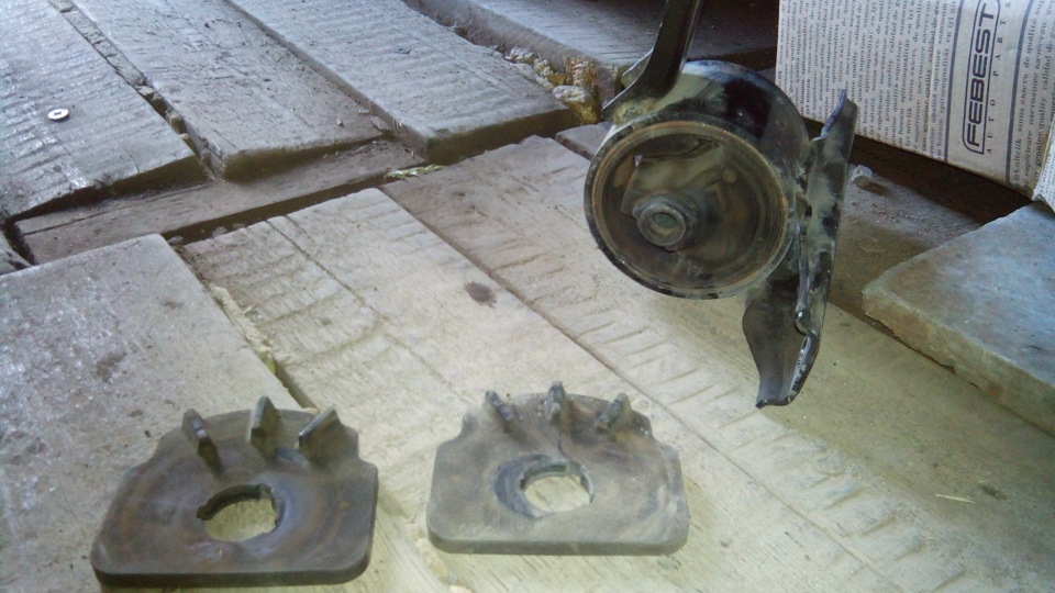
34. Before lifting the engine, check that all cables, wires (electrical connectors), hoses and other connections are disconnected from it.
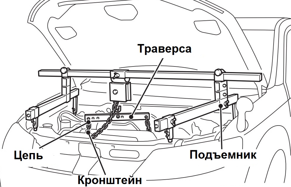
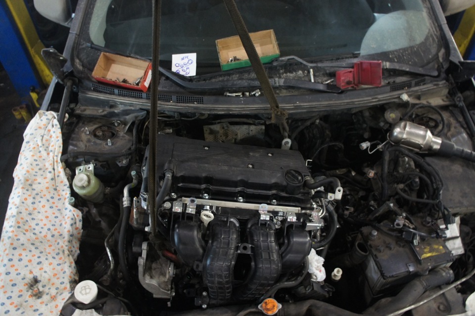
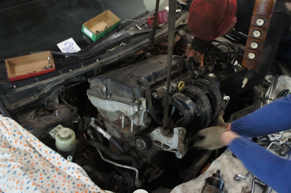
35. Fasten the engine to the yoke and hang it from a hoist or similar device.
36. Now you can remove the engine with your own hands. Slowly lift the engine assembly up from the engine compartment so that it does not move to the side.
Engine installation
Note:
In the case of replacing the engine assembly, use the scanner to reset the adaptations of the engine management system.
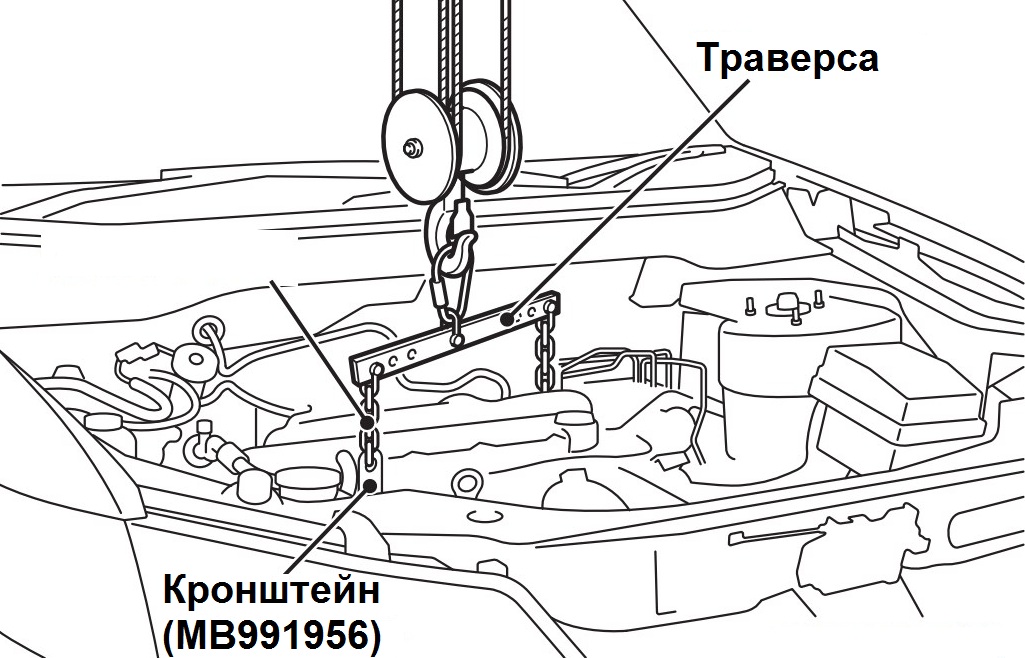
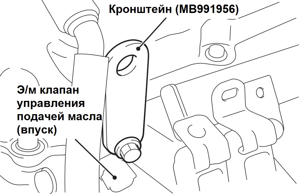
1. Install a special bracket (plate, kn MB991956) on the cylinder head in the place shown in the figure.
2. Fasten the traverse on the engine to the installed bracket and hang it on a hoist or other lifting mechanism (see photo item 35 above).
3. Using the lifting mechanism, slowly lower the Peugeot 4007 engine assembly into the engine compartment so that it does not move to the side.
Note:
Be careful not to damage the hoses, wiring harness and connectors when installing the engine.
When installing the engine, carefully check that the wires, tubes, hoses and wire connectors are connected correctly, that they are not pinched, twisted, damaged, etc.
4. Place a jack under the engine by inserting a piece of wood between the jack foot and the engine oil pan.
Note:
Be careful not to deform the oil pan when supporting the power package with a rolling jack.
5. While supporting the engine with a jack, disconnect the hoist.
6. Using a jack, adjust the position of the engine and install the support, tighten the nut and fastening bolts to the rated torque.
Note:
The tightening torque of the nut and bolt of the support to the engine support bracket is 66 ± 7 Nm.
The tightening torque of the support mounting bolt to the body is 50 ± 5 Nm.
7. Install special devices for engine suspension required when installing the gearbox (see photo item 31 above).
8. Remove from under the oil pan the jack installed to support the engine assembly.
9. Establish a wire of "weight" in situation, as it is shown in drawing.
10. Tighten the alternator mounting bolt to a nominal torque of 44 ±10 Nm.
11. Reinstall the removed gearbox/CVT and intake manifold .
12. Install the air conditioning compressor and the electromagnetic clutch assembly on the engine, tighten the fastening bolts with a nominal torque of 23 ± 6 Nm in the sequence shown in the figure.
13. Install the power steering pump and accessory drive belt .
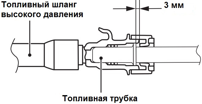
14. Apply some clean engine oil to the fuel line and connect the high pressure fuel hose.
Note:
After connecting, pull the high pressure fuel hose slightly in the direction of disconnection and check that it is securely installed. Check that the play in the connection does not exceed 3 mm.
15. Install the restrictor securely.
16. Connect vacuum hoses, and also connect a hose of system of cooling to the valve of ventilation of crankcase gases.
17. Connecting the upper / lower radiator hose.
17.1.1 (models produced before 03.2009) When connecting the radiator hose, put the hose on the branch pipe until it stops against the protrusion of the branch pipe, then tighten the clamp.
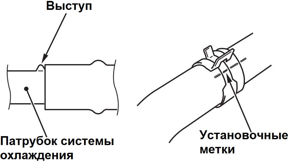
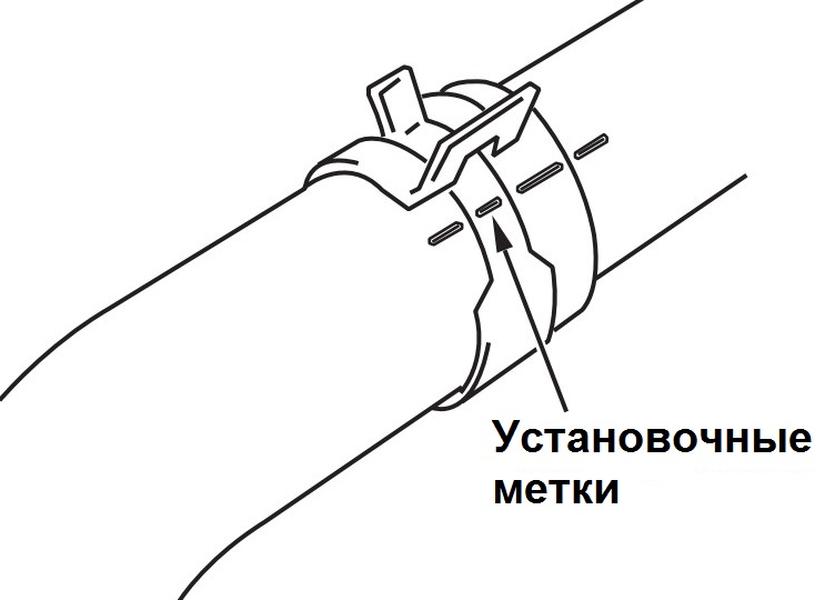
17.1.2 The hose clamp should always be installed in the position in which the clamp was previously installed. Therefore, before installing the clamp, align the alignment marks on the hose clamp and hose, then connect the hose.
17.2.1 (models from 03.2009) Install a new clamp on the radiator hose.
Note:
To avoid rust, do not use a hose clamp that has been removed and has a broken tooth.
17.2.2 When connecting the radiator hose, put the hose on the branch pipe until it stops against the protrusion of the branch pipe.
17.2.3 Loosen the clamp tooth to compress the hose with the clamp and secure it to the nozzle.
Note:
The hose clamp should always be installed in the position in which the clamp was previously installed.
18. Establish other removed details in sequence, return to removal.
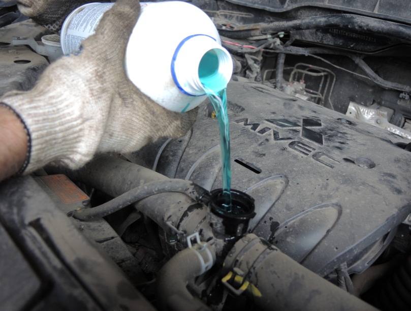
19. Fill the transfer case oil (4WD models), oil (manual transmission) or working fluid (CVT) in the gearbox, engine oil (see first photo below) and coolant (see second photo below).
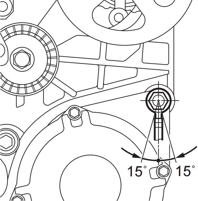
20. Check accessory drive belt tension as described here .
21 . After completing the installation of the parts, start the engine, let it run for a few minutes, and check for fuel and coolant leaks at the connections.
The article is missing:
- Tool photo
- Photo of parts and consumables
Source: carpedia.club