![1 generation [2003 - 2007]](/uploads/Mitsubishi_Outlander_I_2003_-_2008_.jpg)
![3 generation [2012 - 2014]](/uploads/3.png)
![XL [2005 - 2012]](/uploads/4d137205da66f_.jpg)


Tools:
- screw jack
- balloon wrench
- Screwdriver flat medium
- Flat brush (thin)
- Wheel chock (shoe)
- Ratchet wrench
- Extension (with cardan)
- Head 10 mm
- Head 12 mm
- Head 17 mm
- Open end wrench 10 mm
- Straight ring wrench 16 mm
- Straight ring wrench 17 mm
- Straight ring wrench 19 mm
- Collar for end nozzle
- Nozzle on the collar 22 mm
- torque wrench
- Pliers
- Hex wrench for fixing the tensioner (or pin)
- Crankshaft pulley fixing tool (fork holder MB990767 and special bolts and MD998719)
- Oil pan puller MD998727
- Adjustable support with screw jack (or lifting device)
- Knife (or scraper)
- Marker
- Funnel
Parts and consumables:
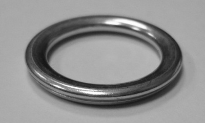
- Engine pan drain plug gasket MD050317
- Cylinder Head Cover Gasket 1035A583
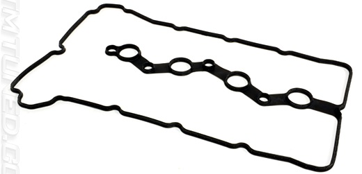
- Technical capacity
- Motor oil
- Rope or wire
- Cleaner (or solvent)
- Degreaser
- wooden block
- Sealant Loctite 5900 or 5970, Three Bond 1217G (1000A923) or 1227D
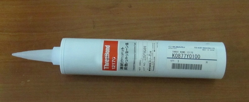
- Dye
- rags
Notes:
The piston of the 1st cylinder is set to the TDC (top dead center) position of the compression stroke so that when carrying out work related to the removal of the camshaft drive circuit, the valve timing is not disturbed. If the valve timing is disturbed, the Outlander HL engine will not work normally.
Work on setting the piston of the 1st cylinder to the TDC position of the compression stroke of the 6B31 engine is described here .
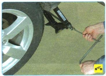
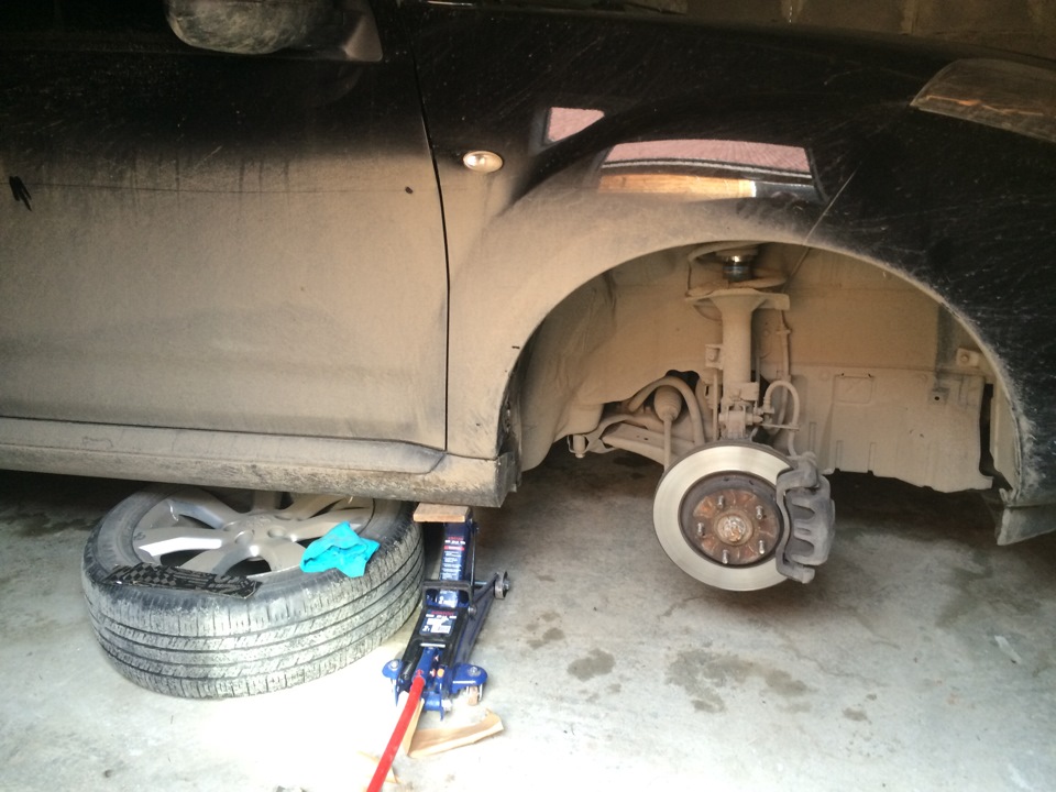
1. Apply the parking brake and place a wheel chock under the left rear wheel. Use a wheel wrench to loosen the right front wheel nuts 1 turn, and then use a jack to hang the right front of the car and completely unscrew the wheel nuts to remove the wheel.

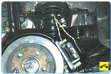
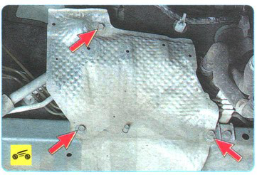
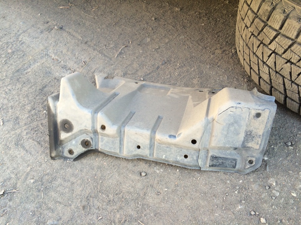
2. Then remove the right side mudguard as described here .
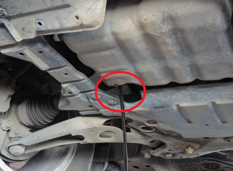
3. Drain the engine oil from the engine.
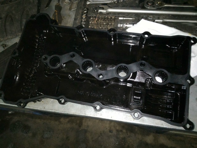
4. Remove the engine cylinder head cover as described here .
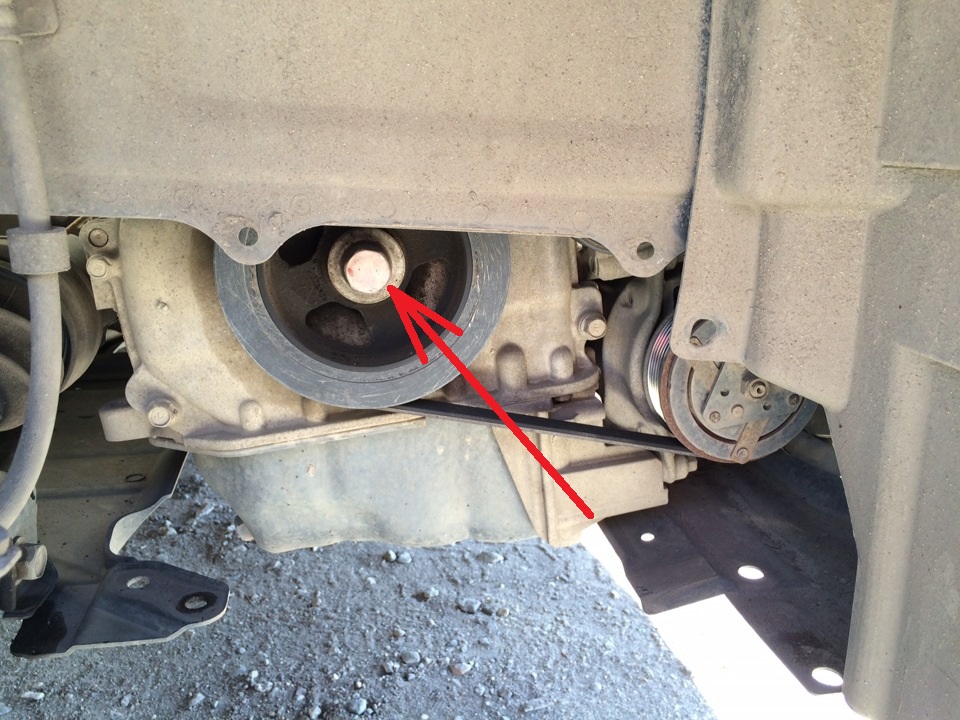
5. The camshaft marks are set using a 22 mm socket wrench. For the accessory drive pulley bolt, turn the crankshaft clockwise until the alignment mark on each camshaft sprocket aligns with the upper plane of the cylinder head, as shown in the figure, and set the first piston to TDC on the compression stroke.
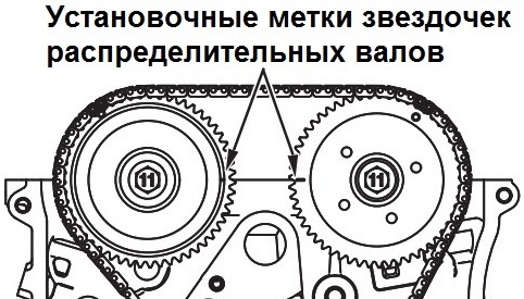
Note:
When installing the first cylinder at TDC, do not turn the crankshaft counterclockwise.
6. Check the alignment of the alignment mark on the crankshaft pulley with the "T" mark on the ignition timing indicator (scale on the timing chain cover).
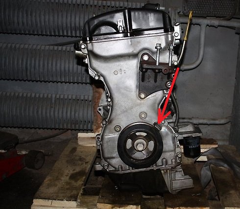
Note:
Additionally, make sure that the alignment mark (key) of the crankshaft sprocket is aligned with the plane of the cylinder block under the main bearing cap. To do this, remove the timing chain cover .
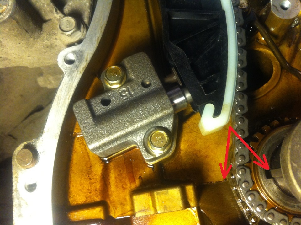
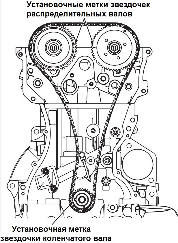
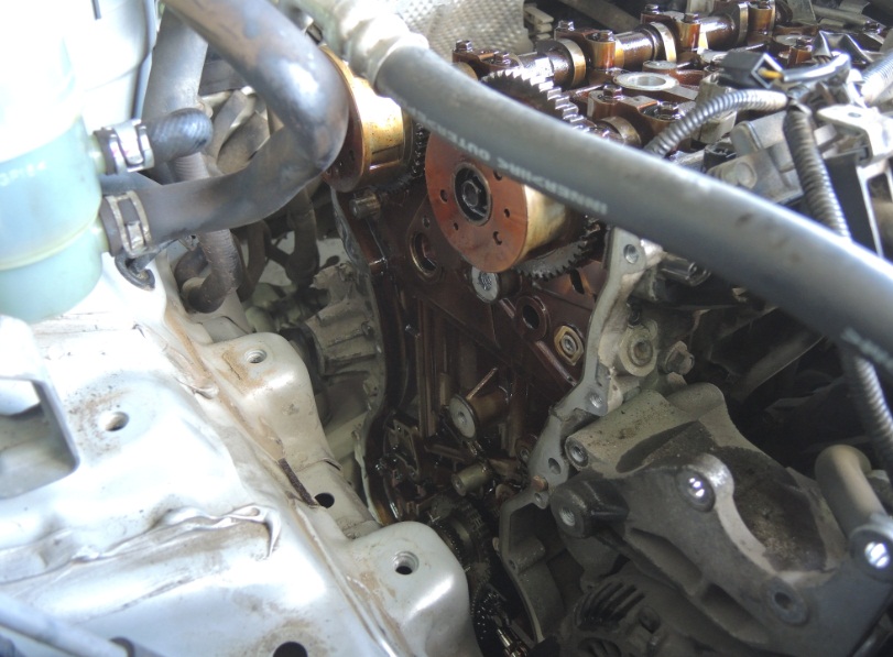
7. If the crankshaft sprocket marks do not match, remove the timing chain and turn the crankshaft clockwise until the marks match.
8. After carrying out work related to the installation of the TDC, you need to assemble all the parts in the reverse order.
The article is missing:
- Tool photo
- Photo of parts and consumables
Source: carpedia.club