![1 generation [2003 - 2007]](/uploads/Mitsubishi_Outlander_I_2003_-_2008_.jpg)
![3 generation [2012 - 2014]](/uploads/3.png)
![XL [2005 - 2012]](/uploads/4d137205da66f_.jpg)

Tools:
- Ratchet wrench
- socket extension
- socket head 10 mm
- socket head 12 mm
- socket head 13 mm
- socket head 19 mm
- socket head 22 mm
- Torx socket (sprocket) T20
- Socket collar
- Open-end wrench 10 mm
- Box wrench curved 8 mm
- Box wrench curved 16 mm
- Screwdriver flat medium
- Phillips screwdriver, medium
- Pliers
- Curved round nose pliers
- Knife (or scraper)
- torque wrench
- Flat brush (thin)
- Chain release pin MB992103
- adjustable wrench
- Camshaft Thrust Measuring Tool
- Micrometer
- Dial head with tripod
- Bench vices with soft metal jaws
- Compressor with hose
- Metal brush
- Funnel
Parts and consumables:
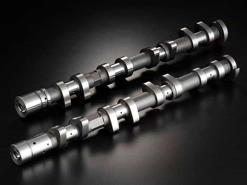
- Inlet camshaft (1015A760 / 1015B319 - for 4B11 engine, 1015A508 / 1015B347 - for 4B12 engine)
- Exhaust camshaft (1015A761 / 1015B321 - for 4B11 engine, 1015A510 / 1015A759 / 1015B349 - for 4B12 engine)
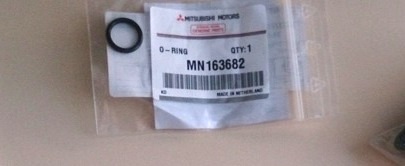
- Oil control valve O-ring MN163682 - 2 pcs.
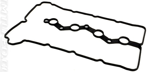
- Cylinder Head Cover Gasket 1035A583
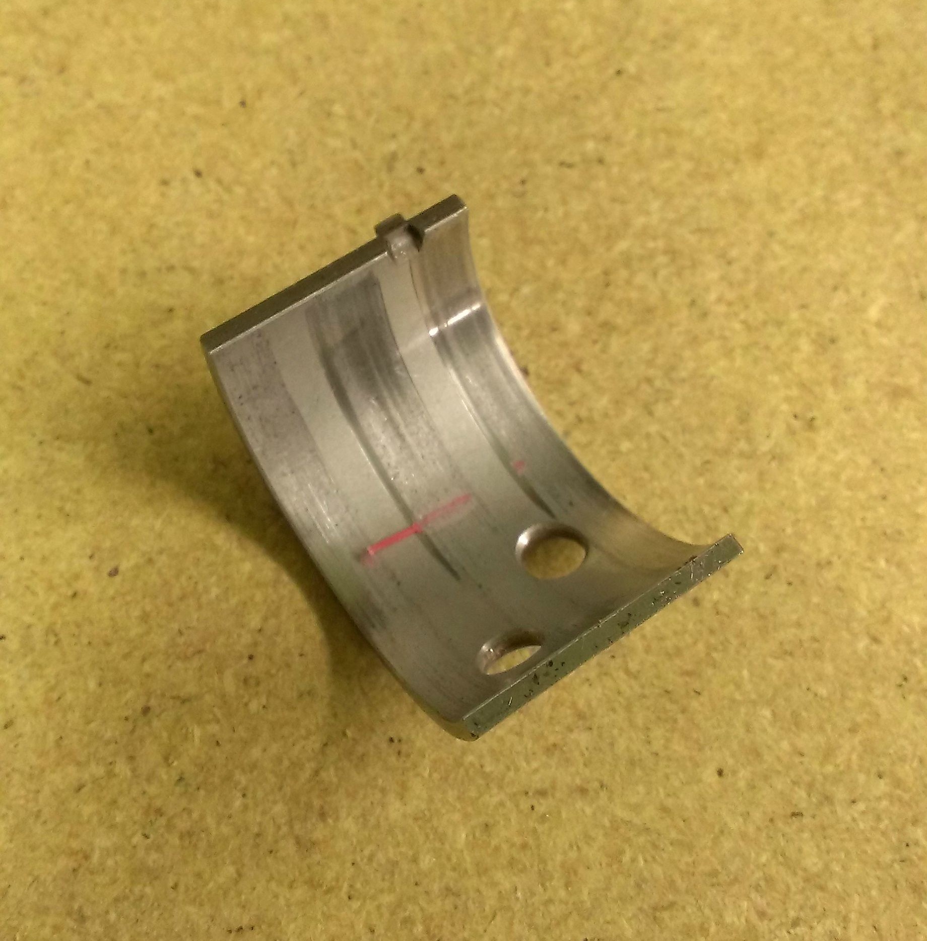
- Camshaft bearing shells 1016A030/1016A031/1016A032
- Intake Camshaft MIVEC Actuator (1147A010 - for 4B11 engine and 1147A005 - for 4B12 engine, if needed)
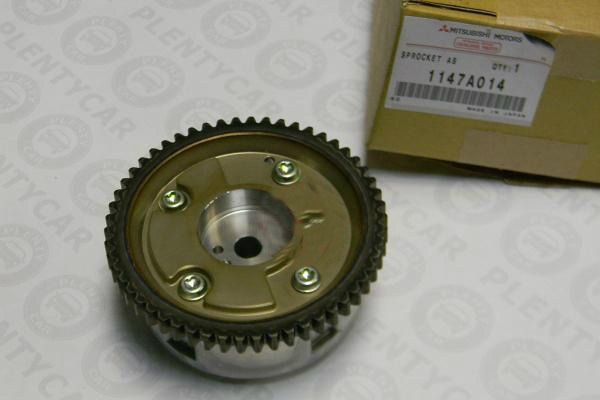
- MIVEC actuator for exhaust camshaft 1147A014 - for 4B11 engine and 1147A013/1147A014 - for 4B12 engine, if required)
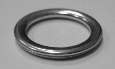
- Engine oil pan plug sealing ring MD050317
- Air filter replacement element (1500A190 (06-07.2009 issue)/1500A023, if needed)
- Air inlet hose (1505A423/1505A630 - for 4B11 engine, 1505A167/1505A423/1505A630 - for 4B12 engine; if required)
- Technical capacity (if necessary)
- Dye
- Rope or wire
- Insulating tape
- Wooden block - 2 pcs.
- Parts cleaner (degreaser)
- Motor oil
- Plastic gauge Plastigauge PL-X (0.018 - 0.045 mm)
- Three Bond Sealant 1217G or 1227D, Loctite 5900
- rags
Notes:
Camshaft replacement is necessary in the following cases:
- the pressure in the engine lubrication system has dropped;
- valve knocking at normal clearances in the valve drive mechanism, caused by increased wear of the camshaft cams due to the use of low-quality engine oil or damage to the oil filter.
The operations for replacing the camshafts of the 4B12 and 4B11 engines are similar.
Removing camshafts
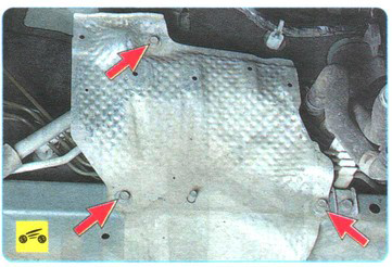
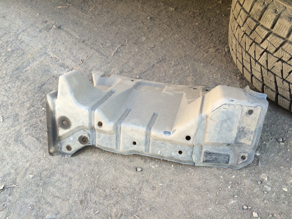
1. Remove engine splash guards (front, bottom, rear and right side) as described here .
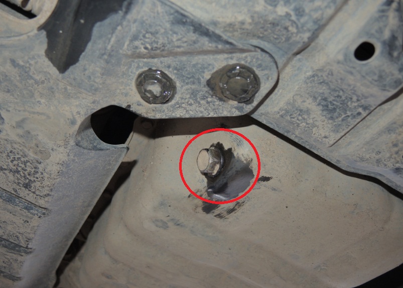
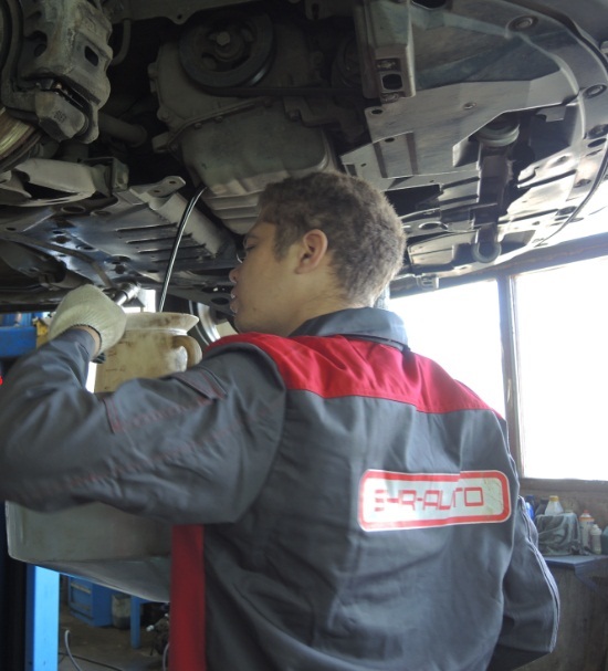
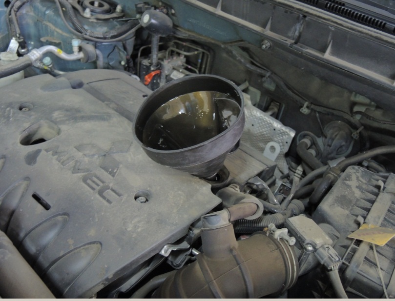
2. If necessary, drain the engine oil into a service container as described in this article .
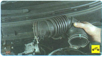
3. Remove the air filter with resonator, air intake and intake hose as described in this article .
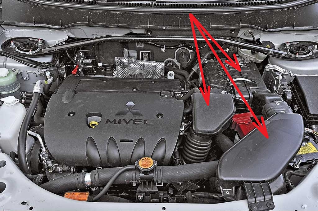
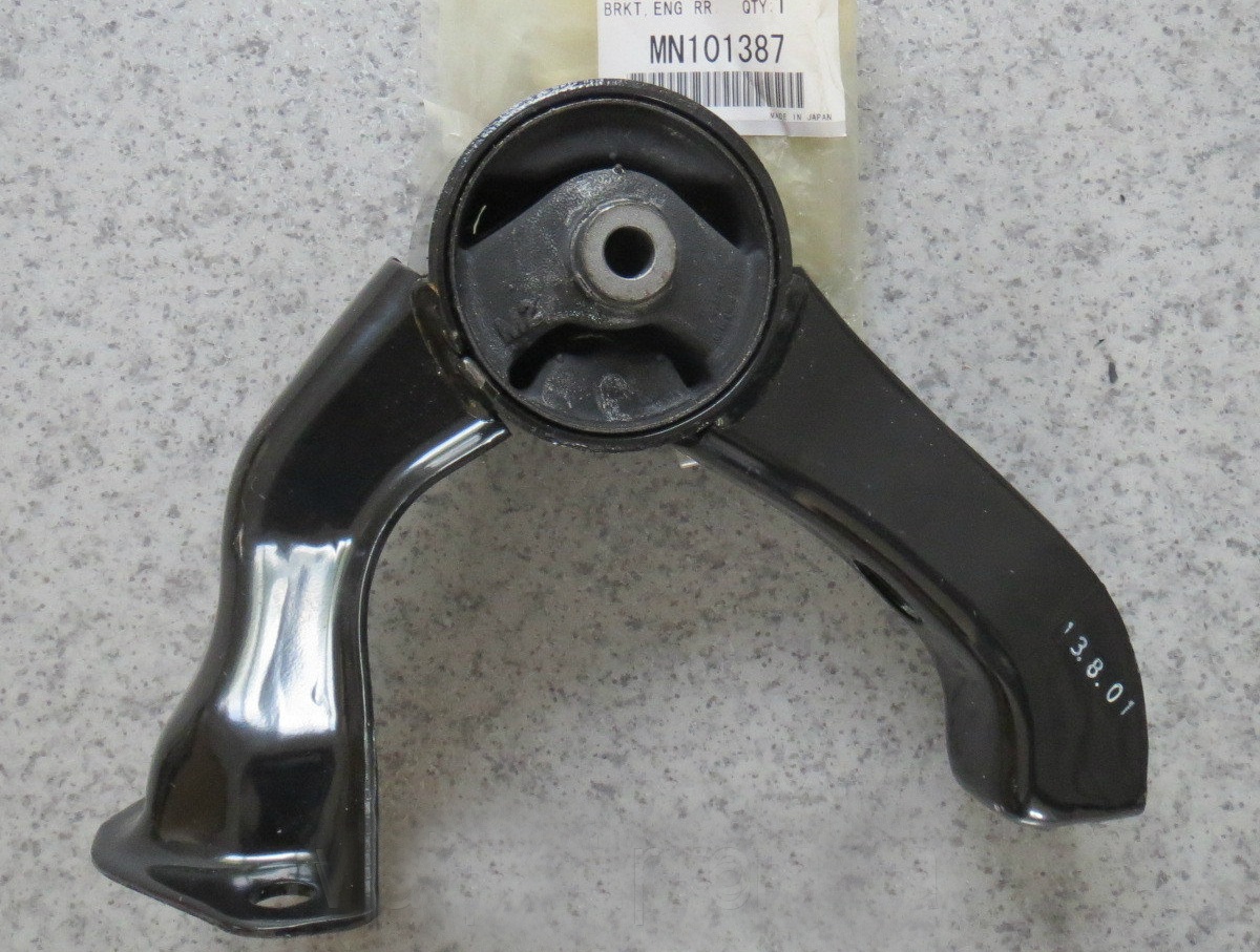
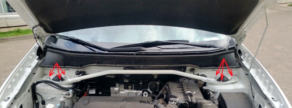
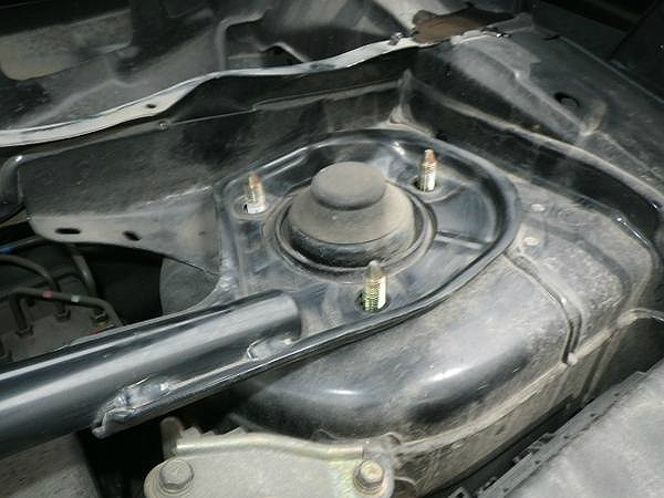
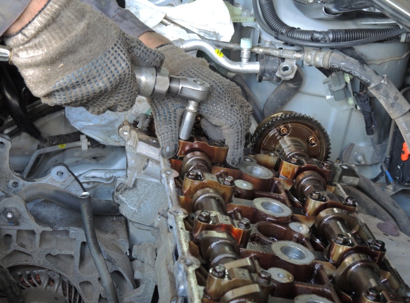
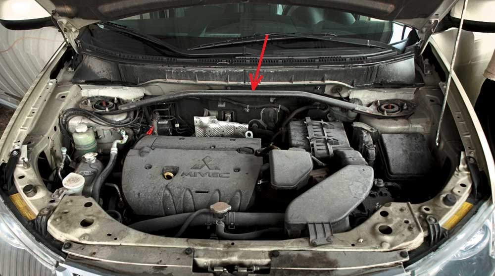
4. Remove the brace by unscrewing the six nuts with a spanner wrench.
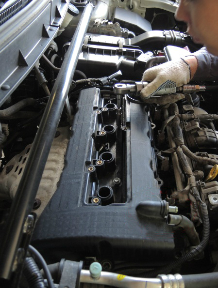
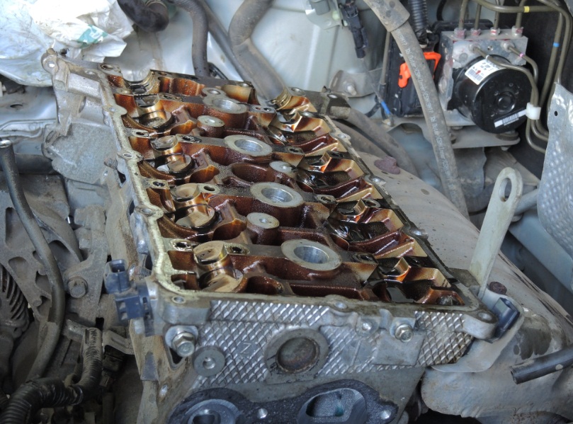
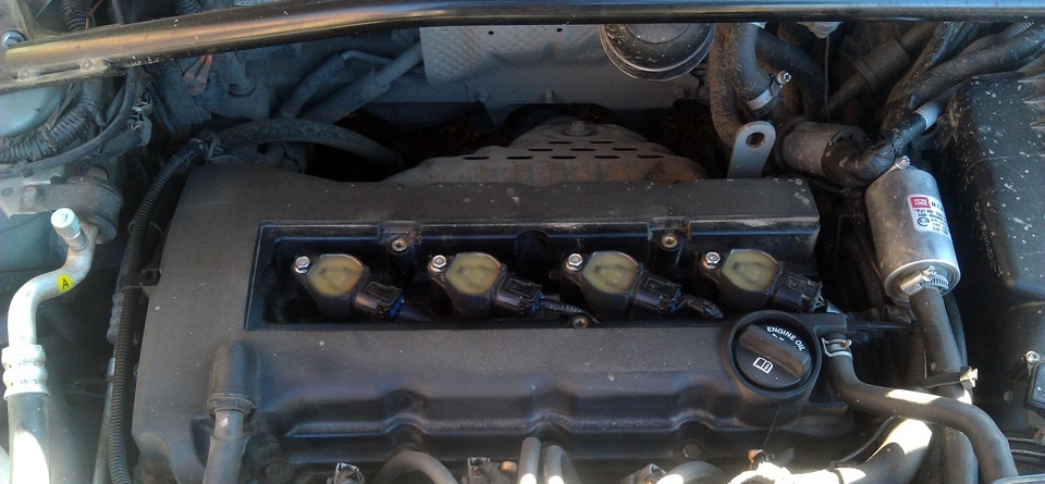
5. Remove the cylinder head cover as described here .
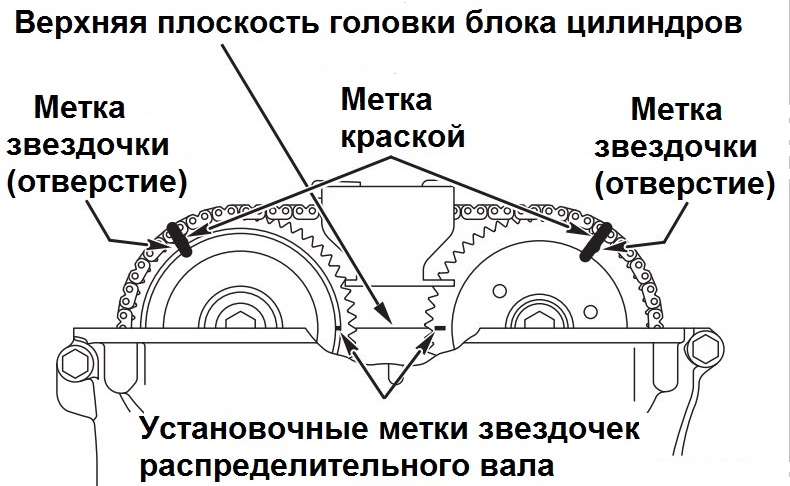
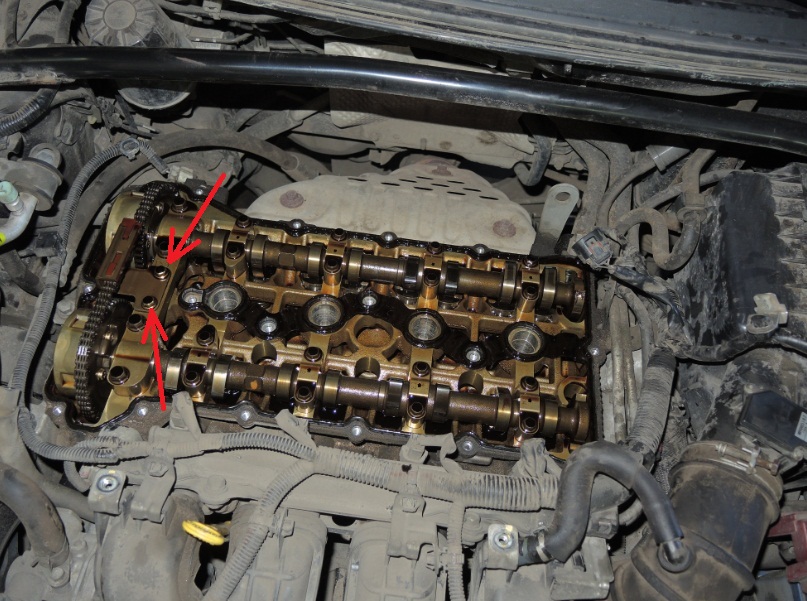
6. Turn the crankshaft clockwise until the alignment mark on each camshaft sprocket is aligned with the upper plane of the cylinder head, as shown in the figure, and set the piston of cylinder No. 1 to TDC of the compression stroke.
Note:
Do not turn the crankshaft counterclockwise.
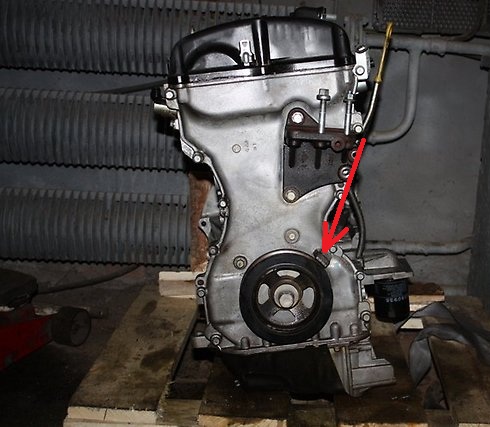
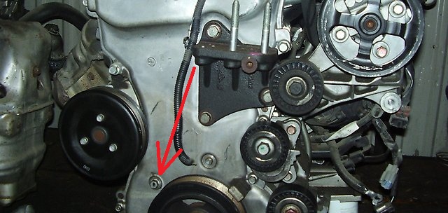
7. Check the alignment of the alignment mark on the crankshaft pulley with the "T" mark on the ignition timing indicator (scale on the timing chain cover, shown on the removed engine for clarity).
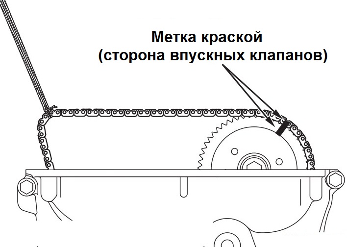
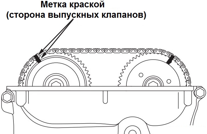
8. Mark with paint the relative position of the camshaft sprocket and the timing chain so that the paint mark passes through the alignment mark (round hole) on the sprocket (see photo p.6).
9. Remove the timing chain guide by unscrewing the mounting bolts.
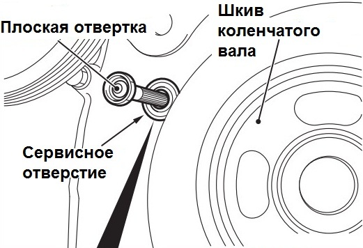
10. Remove the service hole bolt in the timing chain cover.
11. Insert a flathead screwdriver into the service hole on the timing chain cover. Press a screwdriver upwards on the ratchet of the timing chain tensioner to release the rack (rod), and hold in this position.
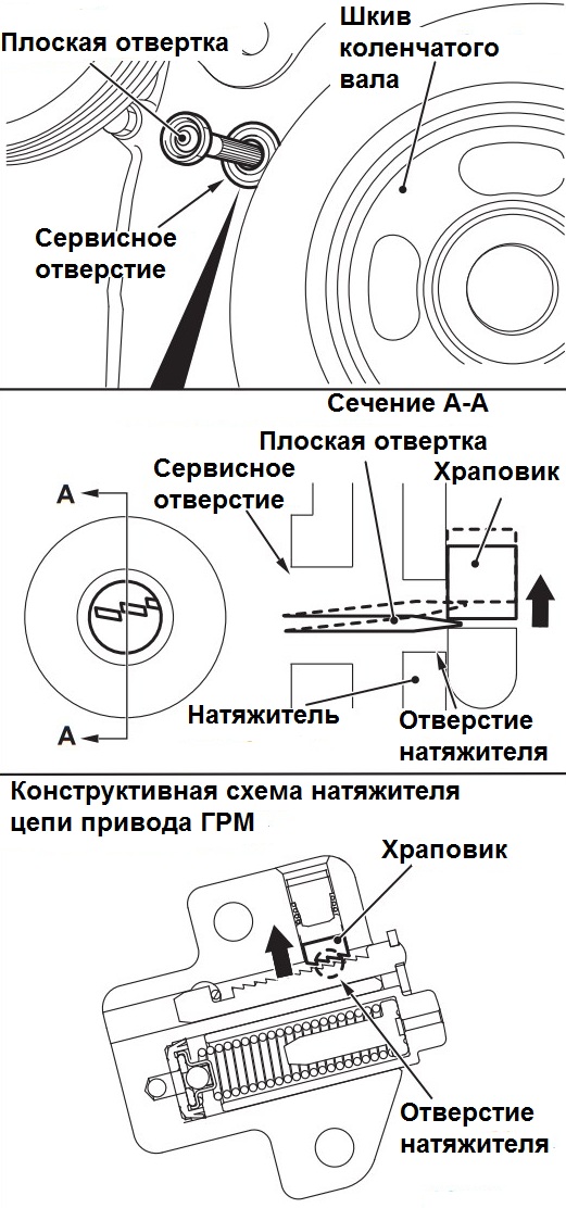
Note:
Press down lightly with the tip of a flathead screwdriver and then up, and insert the screwdriver into the tensioner to release the stem.
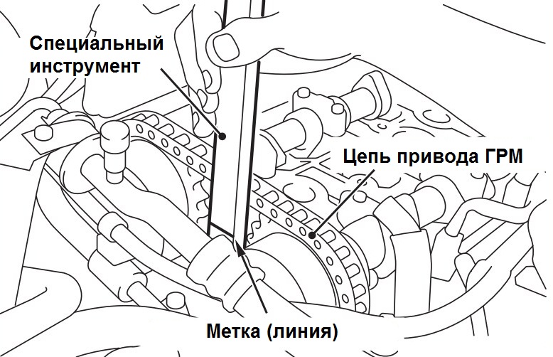
12. With the tensioner rod released, insert inside the timing chain cover, along the tension side of the chain, the special tool (chain release pin MB992103) to the indicated mark on the tool (direction "A" indicated in the figure below).
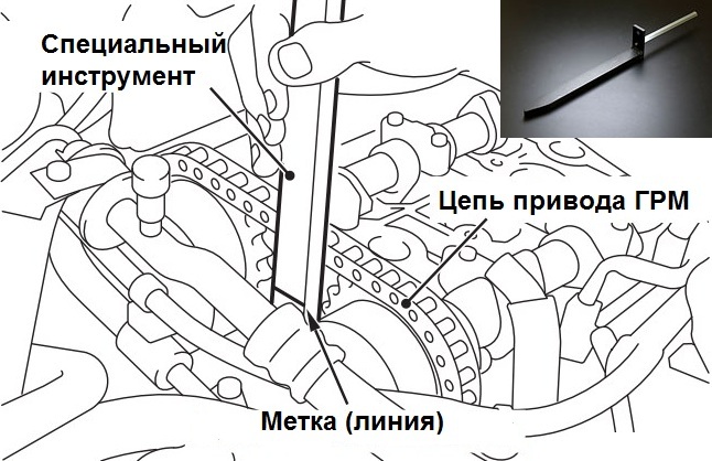
Note:
To prevent damage to the timing chain and tensioner shoe, when inserting the special tool to release the tension of the chain inside the timing chain cover, pay attention to the location of the chain. Do not insert the special tool below the indicated mark (line).
If the tensioner rod is not completely released, then the special tool cannot be inserted up to the indicated mark. Do not insert the special tool forcibly, repeat the procedure for releasing the tensioner rod.
With the tensioner rod released, insert the special tool along the tension side of the chain according to the shape of the tool tip.
The special tool must be smoothly inserted into the position where the mark on the tool is aligned with the top plane of the timing chain cover.
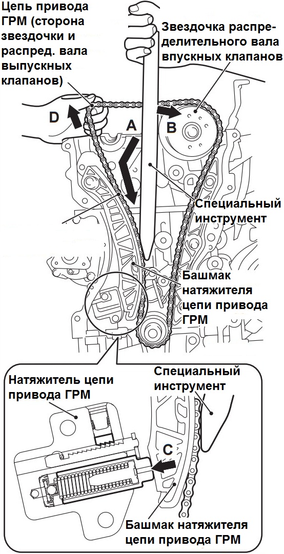
13. With the special tool inserted up to the indicated mark, apply force to the special tool in the direction of the intake camshaft sprocket (direction "B" shown in the figure below). Press the tensioner shoe against the tensioner to retract the stem (direction "C" indicated in the figure) and hold in this position.
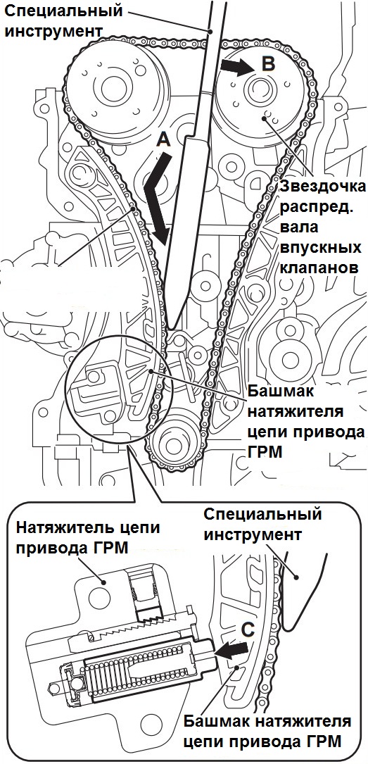
14. Remove the flathead screwdriver used to depress the ratchet to lower the chain tensioner rod.
15. With the tensioner shoe pressed out with a special tool, install the wrench on the hex of the exhaust camshaft, then turn the camshaft so that the chain sags between the sprockets.
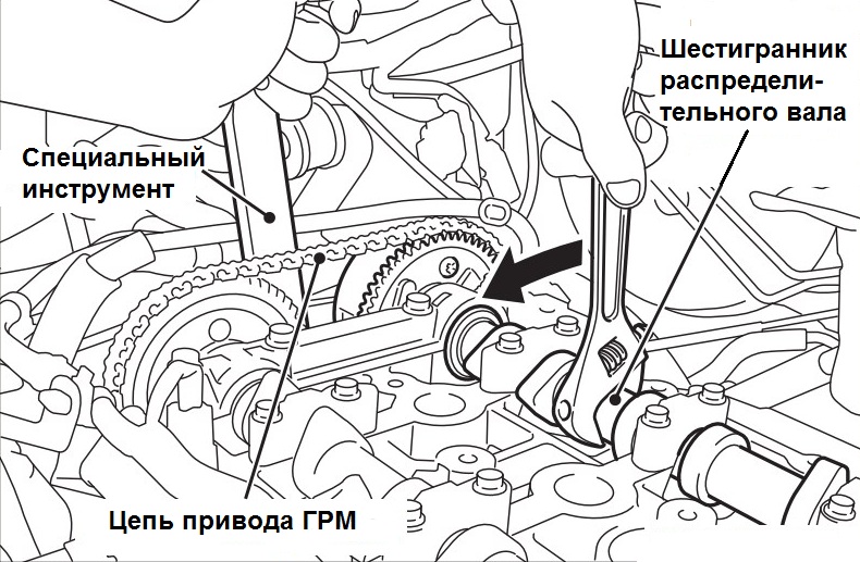
Note:
The timing chain may be pinched between other parts; after the chain has slack between the sprockets, never turn the crankshaft.
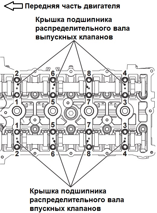
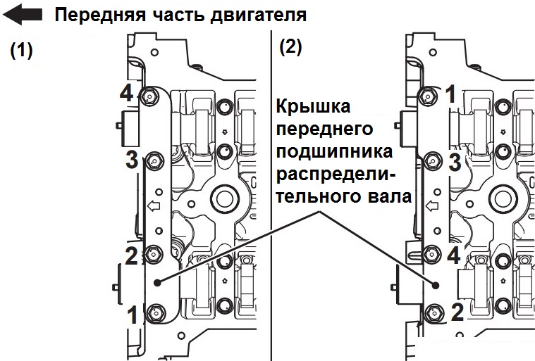
16. Loosen the bolts securing the front camshaft bearing cover in the sequence of numbers shown in the figure, and remove the cover together with the upper camshaft bearing shells.
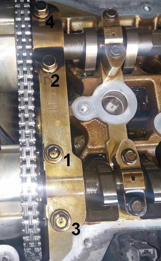
Note:
Be careful not to drop the camshaft bearing shells.
17. Loosen the camshaft bearing cap bolts in four or five steps in the sequence shown in the figure below.
Note:
If the camshaft bearing cap bolts are loosened in one go, the movement of the camshaft under the force of the valve springs can lead to the bolts pulling out and damage to their threads.
18. Slightly lift the working part of the camshaft, using the chain slack between the sprockets, and remove the sprocket and exhaust camshaft assembly from the bearing bed on the cylinder head.
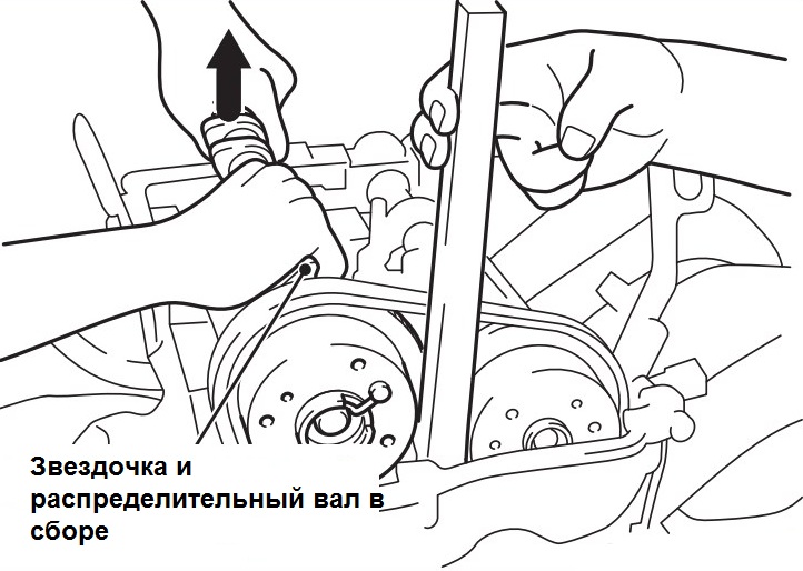
19. Remove the timing chain from the camshaft sprocket towards the timing chain cover, then remove the sprocket and exhaust camshaft assembly towards the working part of the shaft.
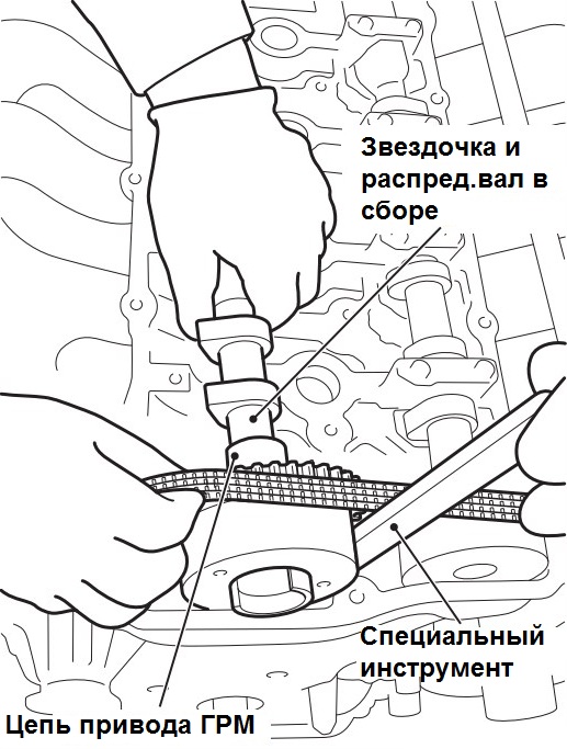
20. Remove the special tool used to depress the tensioner shoe.
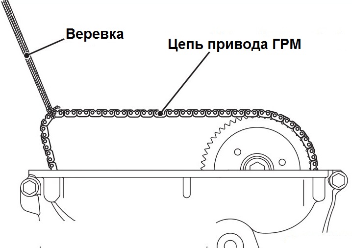
21. After removing the sprocket and exhaust camshaft assembly, to prevent the chain from falling into the timing chain cover and the chain from jumping off the crankshaft sprocket, hang the timing chain with a rope.
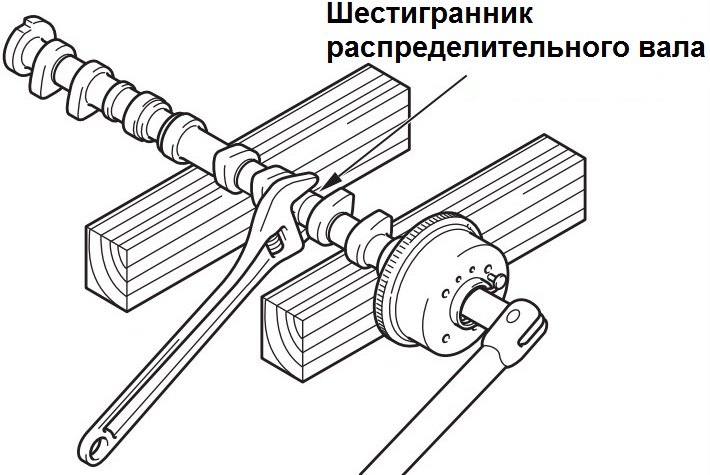
22. Secure the camshaft against rotation with a hexagon wrench on the camshaft.
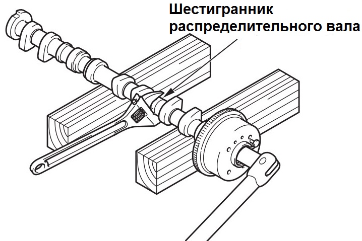
23. Remove the mounting bolt and remove the sprocket (MIVEC actuator assembly) from the camshaft.
24. Remove the lower bushing of the exhaust camshaft from the bearing bed.
25. Similarly, remove the intake camshaft assembly and remove the sprocket from the shaft (item 17-24).
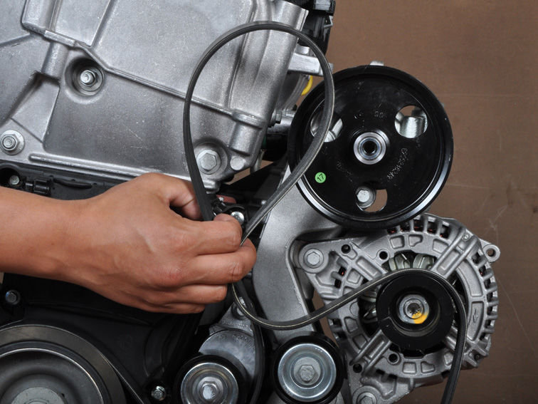
26. Remove the engine accessory drive belt as described here .
27. Remove the power steering pump assembly from its bracket along with the connected hoses.
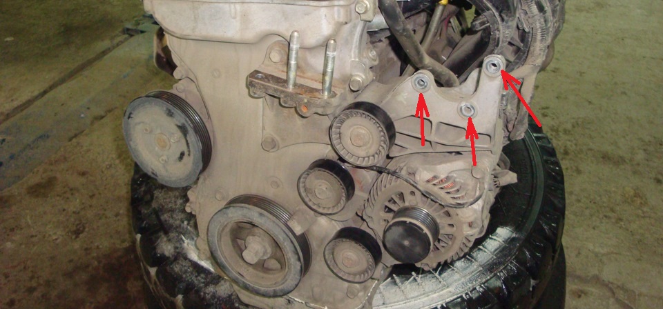
Note:
After removal, use a wire or rope to hang the power steering pump assembly with hoses on the body in a place where they will not interfere with the removal and installation of other parts.
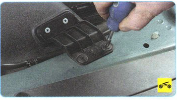
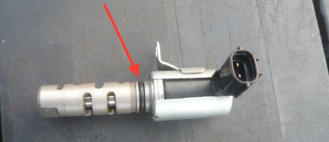
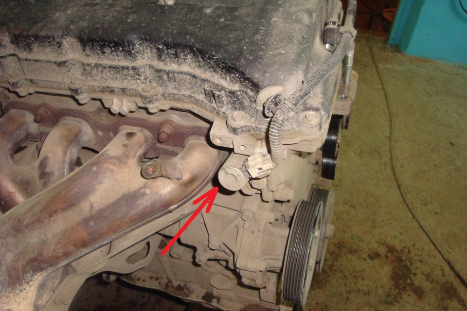
28. Disconnect the wiring harness from the oil control solenoid valve connector on the exhaust side and unscrew its fastening bolt using a 10 mm socket.
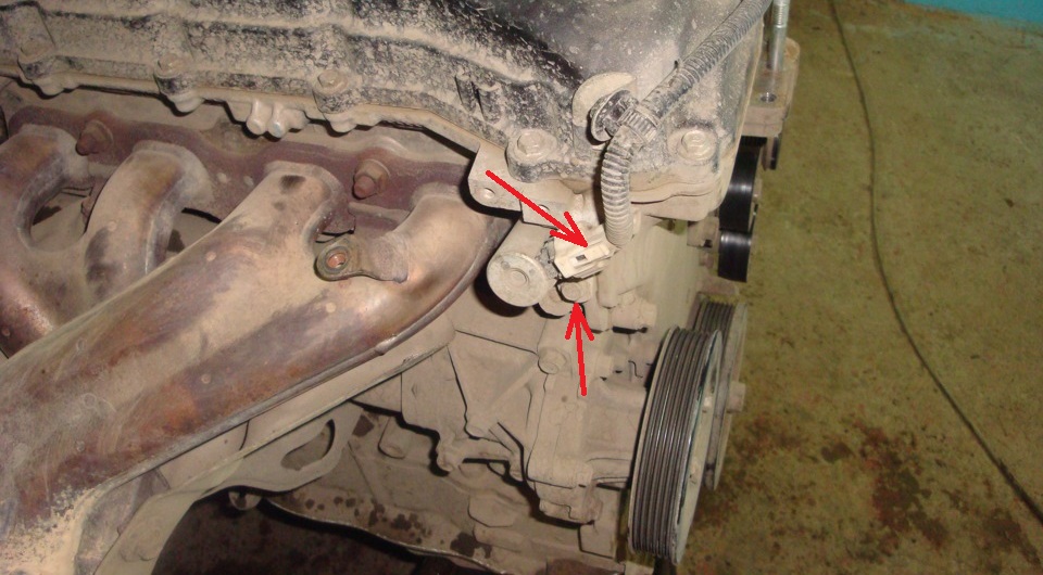
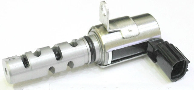
29. Remove the valve with O-ring from the cylinder head.
Note:
After removing the oil control solenoid valve, be careful not to allow dust and other foreign particles to enter the oil passage through the solenoid valve installation hole.
30. Similarly, remove the other solenoid valve (with an O-ring) for controlling the oil supply from the intake valves.
Checking the camshafts
Note:
When replacing the cylinder head and/or exhaust camshaft, the correct camshaft bearing shells must be selected.
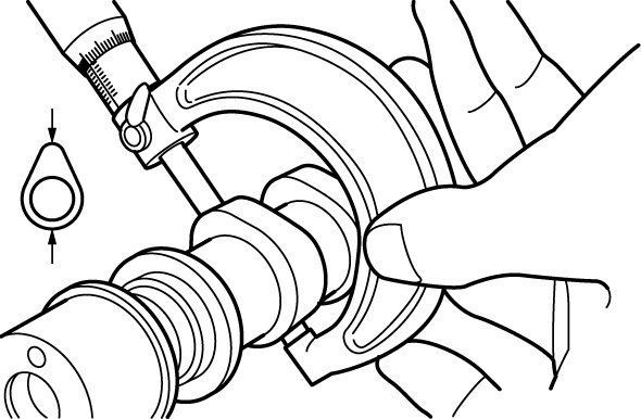
1. Measure the camshaft end play when the shaft is installed in the cylinder head.
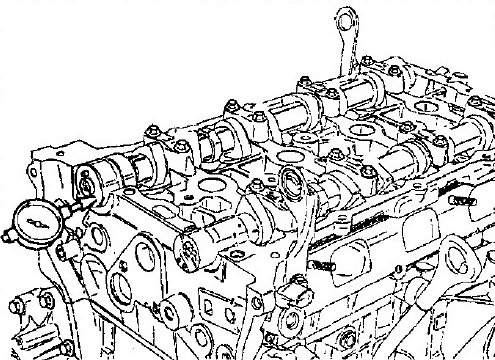
Note:
Axial clearance should be: nominal 0.04-0.16 mm; maximum allowable 0.20 mm. If the camshaft end play is greater than the limit, replace the camshaft and/or cylinder head.
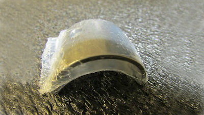
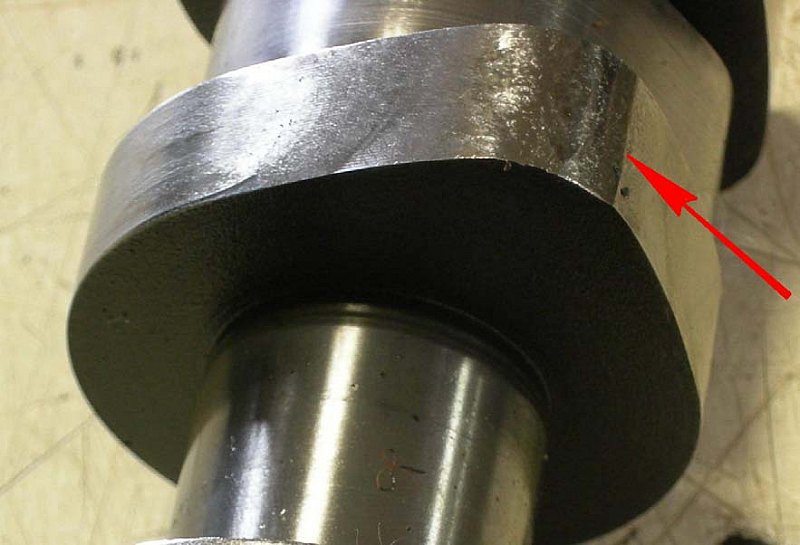
2. Check the camshaft journals for scoring and wear.
Note:
If scoring is present or if the shaft journals are worn, replace the camshaft.
3. Measure the diameters of the camshaft bearing journals with a micrometer.
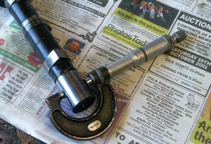
Note:
The diameter of the camshaft bearing journal must be:
Inlet valve shaft: journal No. 1 - 30 mm; necks No. 2, 3, 4 and 5 - 24 mm. Exhaust valve shaft: neck No. 1 - 36 mm; necks No. 2, 3, 4 and 5 - 24 mm.
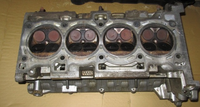
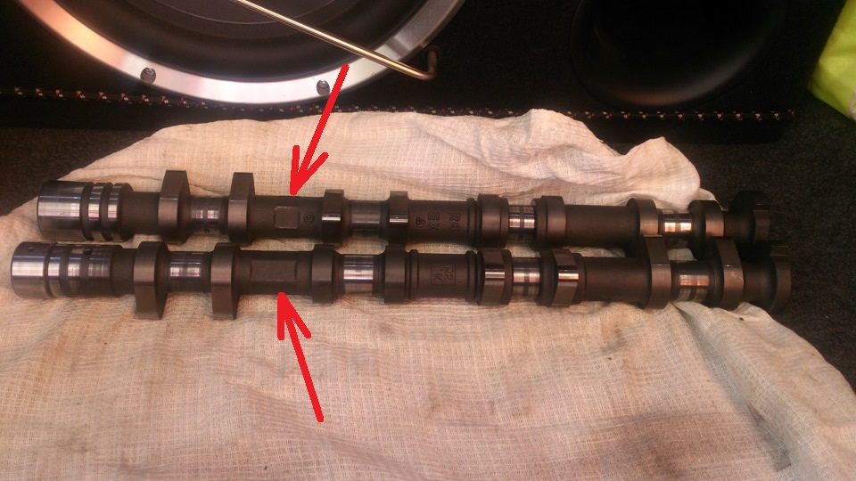
4. Check the surface of the protruding and rear part of the camshaft lobes for damage or significant wear.
Note:
If the shaft cams are damaged or there is significant wear visible to the naked eye, then replace the Mitsubishi Outlander HL camshaft.
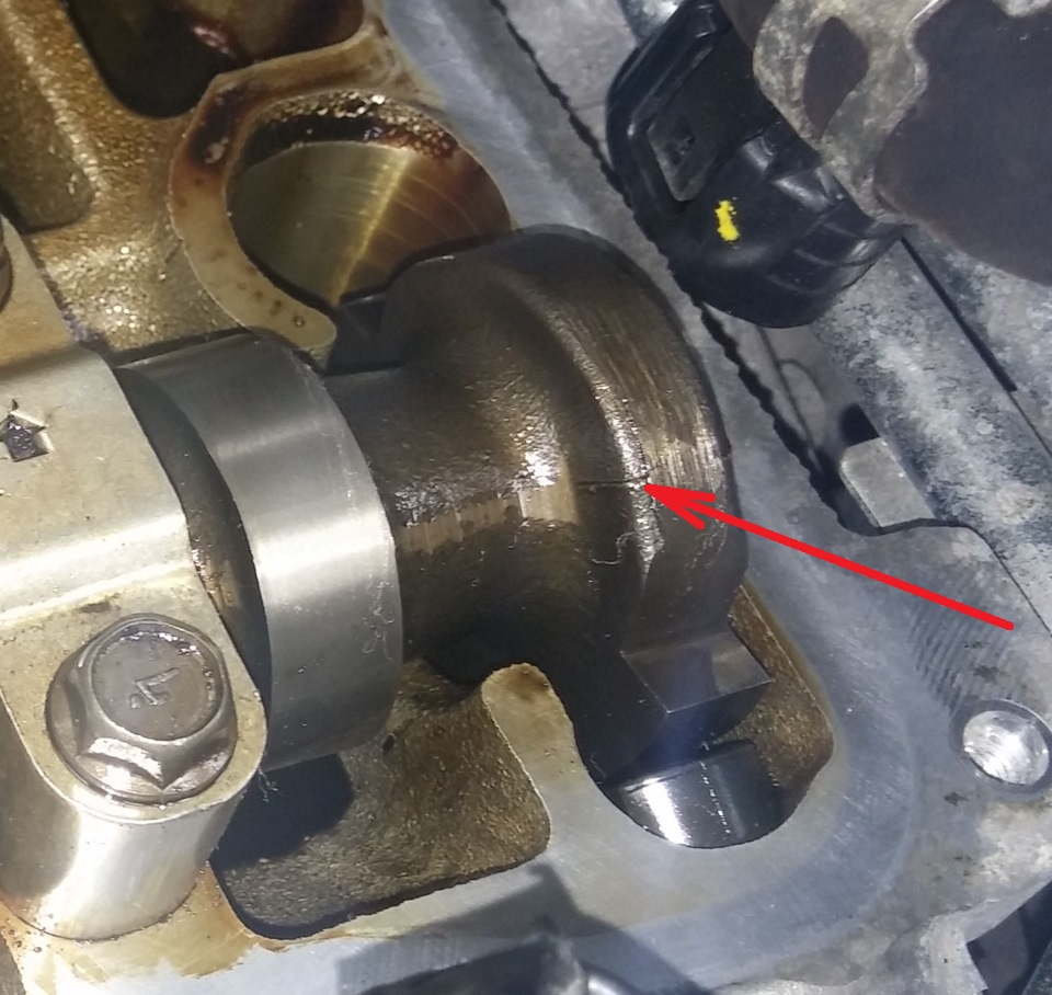
Crack on the camshaft
5. Using a micrometer, measure the height of the camshaft lobes.
Note:
If the measured value is less than the limit value, replace the camshaft.
Intake camshaft cam height: nominal value 44.10 mm; the maximum allowable value is 43.60 mm.
Height of the cams of the exhaust camshaft: nominal value 45.00 mm; the maximum allowable value is 44.50 mm.
6. Check the condition of the bearing surfaces (bed) of the camshaft on the cylinder head and the condition of the working surface of the camshaft bearing caps (no damage, significant wear).
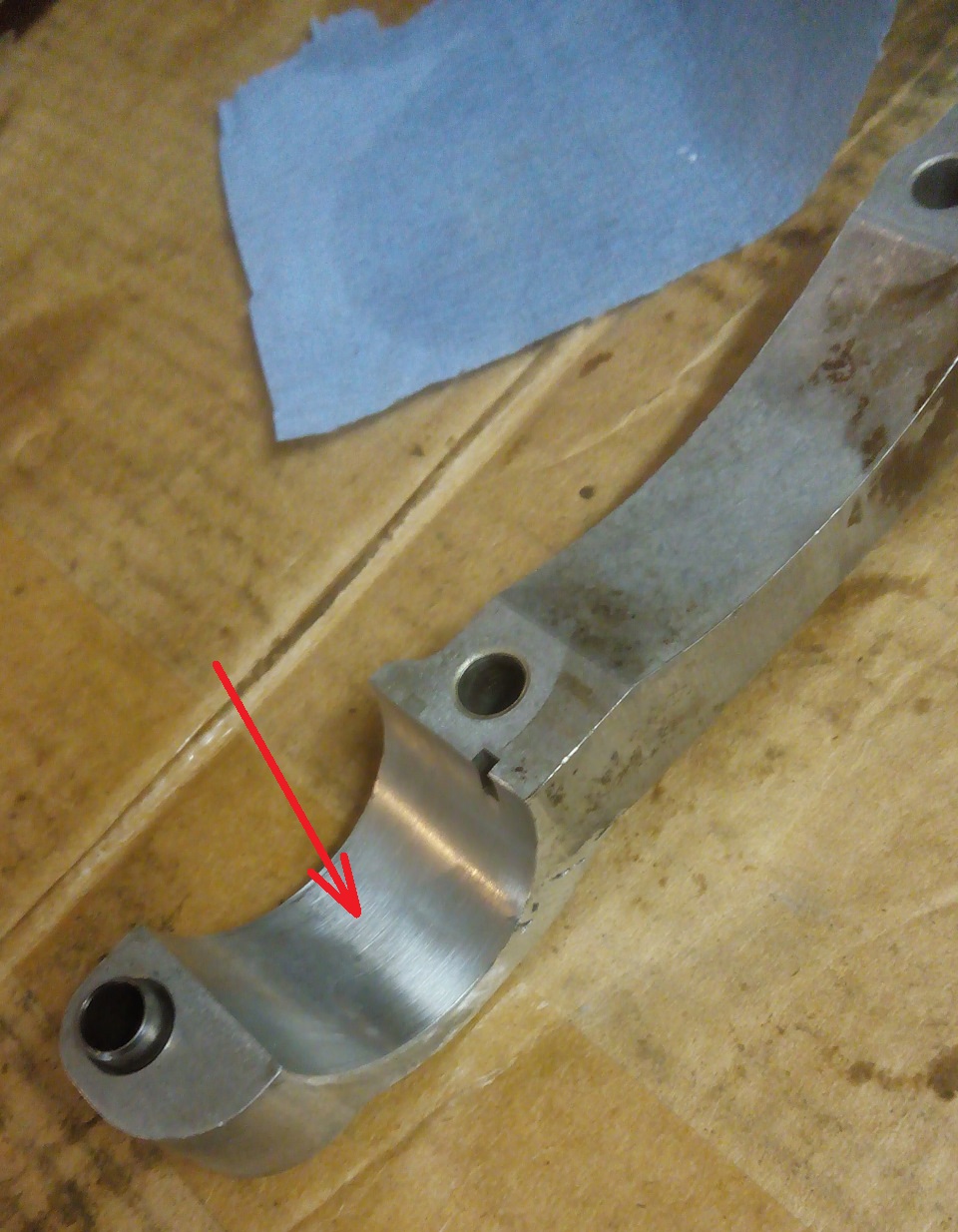
Note:
If there is damage (burrs) or significant wear on the indicated surfaces, replace the cylinder head and/or camshaft.
7. Determine the camshaft oil clearance.
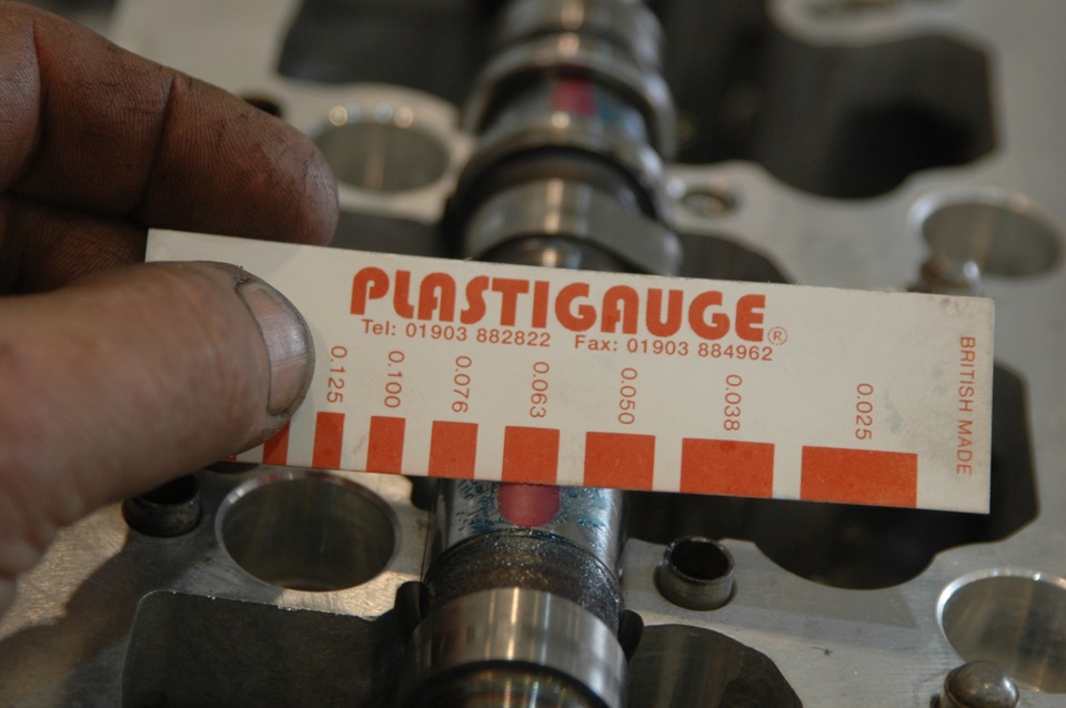
Note:
To simplify the measurement of the oil clearance in the camshaft bearings, use the plastic gauge method. Checking the camshaft using the plastic gauge method is described here .
The oil clearance should be 0 - 0.032 mm. If the clearance in any bearing exceeds the nominal value, then replace the camshaft and / or cylinder head.
8. Establish a camshaft on support (on extreme basic necks). Measure the runout of the shaft on the middle neck.
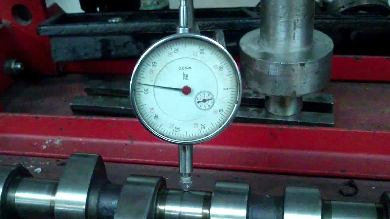
Note:
If the runout exceeds the limit, replace the camshaft.
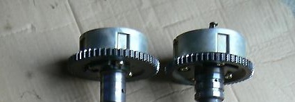
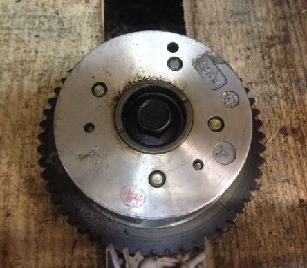
Checking MIVEC Actuators Assemblies
Note:
Never disassemble the MIVEC actuator as it is not repairable.
If the MIVEC actuator fails, replace it.
The check is made with the MIVEC actuator installed on the camshaft.
1. Check that the MIVEC actuator is not rotating.
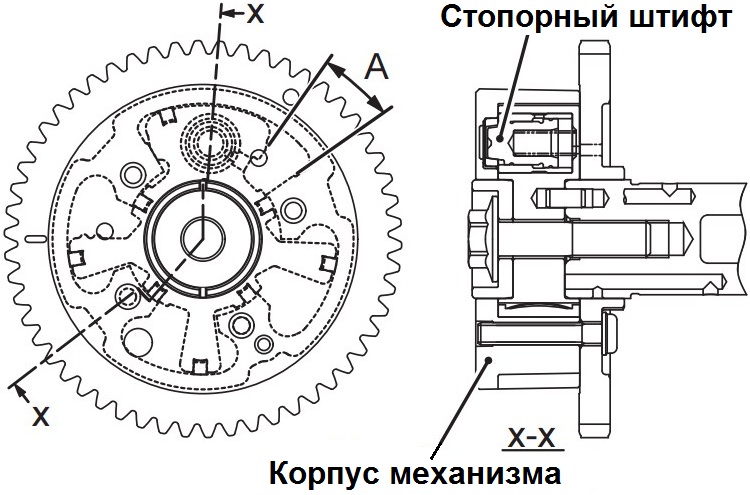
2. Use duct tape to cover all holes on the camshaft through which the MIVEC actuator is controlled.
Note:
Hole "A" - advance control channel (oil supply channel for turning the body of the MIVEC mechanism in the direction of advancing the opening / closing of the valves).
Hole "B" - delay control channel (oil supply channel for turning the body of the MIVEC mechanism in the direction of delaying the opening / closing of the valves).
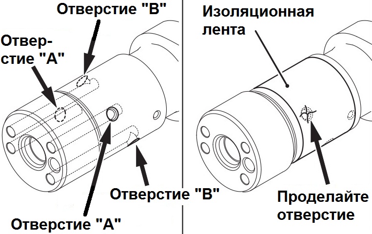
intake valve shaft
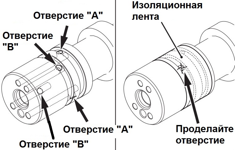
Exhaust valve shaft
3. Make a hole in the tape shown in the figure above to open one of the control channels:
Inlet camshaft - to access the advance control hole.
Exhaust camshaft - for access to the lag control hole.
4. Fix the camshaft in a vice for the hexagon on the shaft.
Note:
Fix the camshaft only by the hexagon, otherwise damage to the bearing journals and cams of the shaft may occur.
5. Supply compressed air to the MIVEC actuator through the hole made in the tape at a pressure of 147-150 kPa.
Note:
Be careful, oil may splatter when supplying air.
Cover the edges of the hole with a rag to prevent oil splashing.
In case of splashing, remove the oil with a rag.
Pressurized air will depress the stop pin when the actuator housing is in the position corresponding to the latest opening and closing of the intake valves (maximum lag angle) or the earliest opening and closing of the exhaust valves (minimum lag angle).
6. Under the conditions in step 5, ensure that the MIVEC actuator housing is rotated by hand in the direction of earlier open/close intake valves or later open/close exhaust valves.
7. Depending on the applied pressure, the housing of the MIVEC actuator can be rotated without applying additional force (without turning it by hand) or, conversely, with excessive force due to air leaks, due to which the locking pin is not fully pressed out.
8. With the exception of the position when the locking pin is not depressed and, accordingly, the mechanism body is installed in the position of the maximum delay in the opening of the inlet valves or the minimum delay in the opening of the exhaust valves, check the range "A" of the actuator mobility. The mechanism is considered serviceable if its body rotates back and forth (left-right) smoothly, without jamming, from the neutral position by the specified value. Also check that there is no noise when the actuator rotates.
Note:
Angle of rotation of the MIVEC actuator of the 4B11 engine from one extreme position to another: for the intake shaft 25°; for outlet shaft 20°.
Angle of rotation of the actuator MIVEC engine 4B12 from one extreme position to another: for the intake shaft 40°; for outlet shaft 20°.
intake valve shaft
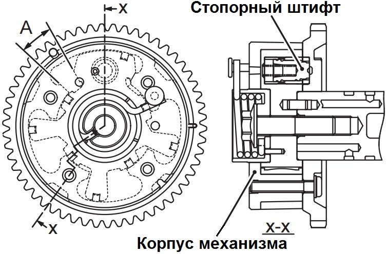
Exhaust valve shaft
9. After completing the test, fully rotate the MIVEC actuator housing in the direction shown below, then stop the compressed air supply to eliminate the depressurization of the lock pin.
Note:
Direction of rotation of the MIVEC actuator housing: intake valve shaft - clockwise; exhaust valve shaft - counterclockwise.
Turning the intake valve shaft MIVEC actuator housing clockwise will set the maximum valve opening and closing delay angle.
Turning the exhaust valve shaft MIVEC actuator housing counterclockwise will set the minimum valve opening and closing delay angle.
10. Completely remove the tape from the camshafts.
Installation of camshafts
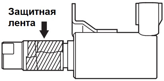
1. Apply a small amount of engine oil to the O-ring and install it to the oil control valve.
Note:
Use only new O-rings for valves.
To prevent damage to the ring gasket, wrap protective tape around the working part of the solenoid valve, on which the oil passages are located, before installation.
2. Install the solenoid valve in the cylinder head.
3. Tighten the valve mounting bolt to a nominal torque of 11 ± 1 Nm.
4. Lubricate the minimum amount of engine oil as shown in the figure on the camshaft and sprocket mounting hole (MIVEC actuator assembly).
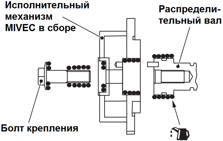
5. Install the MIVEC actuator assembly onto the camshaft.
6. Verify that the MIVEC actuator assembly is properly seated on the camshaft (camshaft pilot pin is seated in the hole on the MIVEC actuator).
7. Secure the camshaft against rotation with a hexagon wrench on the camshaft and check that the actuator does not rotate.
8. Apply a minimum amount of engine oil as shown in the illustration below to the threads and head flange of the MIVEC actuator mounting bolt.
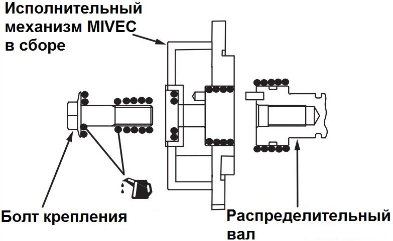
9. While holding the camshaft from turning, tighten the MIVEC actuator assembly mounting bolt to a nominal torque of 59 ± 5 Nm.
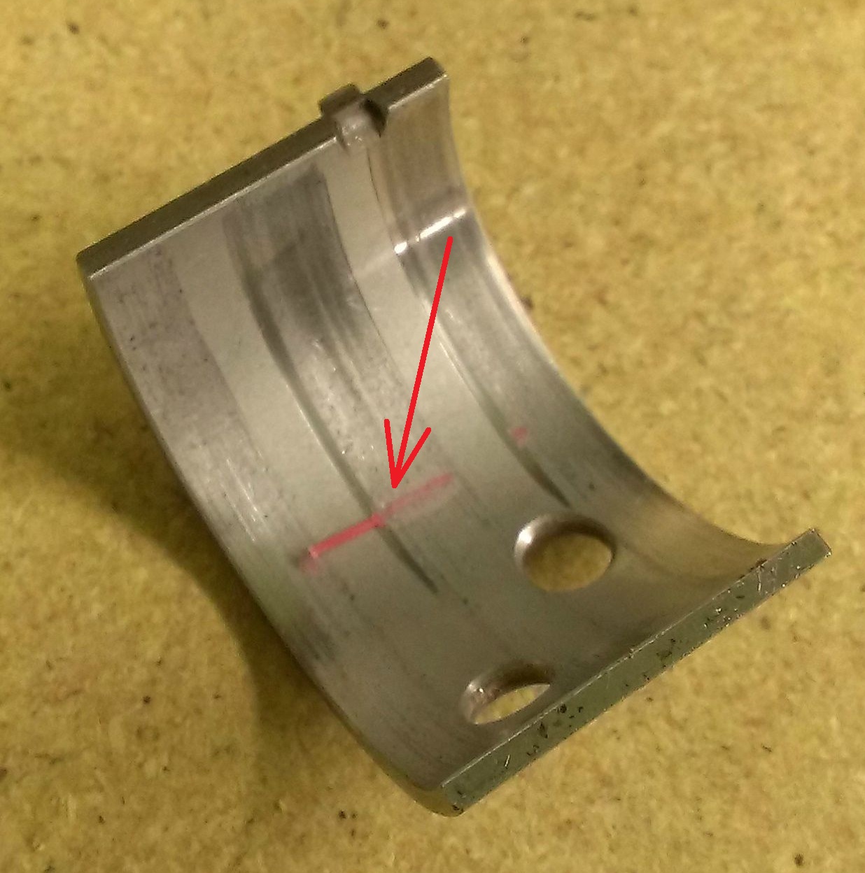
10. When replacing the cylinder head and / or the exhaust camshaft, it is necessary to select the appropriate camshaft liners. When replacing the camshaft bearing shells, select them according to the table below in accordance with the size group
(identification mark) of the bearing hole diameter printed on the front bearing cap and the size group (color or identification mark) of the bearing shells.

Note:
The size group mark for the diameter of the camshaft journal is applied to the front bearing cap.
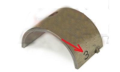
Numeric identification mark on insert
Color identification label on insert
11. Align the paint mark on the camshaft sprocket with the paint mark on the timing chain made during removal and install the chain on the sprocket.
Note:
When reassembling, apply some clean engine oil to the bearing journals and camshaft lobes.
12. Lay an asterisk and a camshaft of inlet valves in gathering on a head of the block of cylinders.
13. Install the camshaft bearing caps.
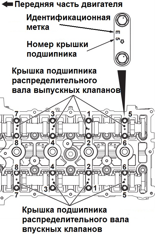
Note:
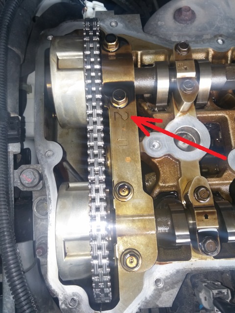
Since the camshaft bearing caps with oil feed and the camshaft bearing thrust caps have the same shape as other bearing caps, for correct installation, check that the identification mark and number of the cap match the installation location (identification of the side of the intake and exhaust valves) and the bearing number:
I - intake camshaft;
E - exhaust camshaft.
14. Tighten the camshaft cover bolts in two or three steps and in the sequence shown in the figure until the nominal tightening torque of 12 ± 1 Nm is reached.
15. Similar to the removal procedure, insert a flathead screwdriver into the service hole on the timing chain cover. Press a screwdriver upwards on the ratchet of the timing chain tensioner to release the rack (rod), and hold in this position.
Note:
Press down lightly with the tip of a flathead screwdriver and then up, and insert the screwdriver into the tensioner to release the stem.
16. Similar to the removal procedure, with the tensioner rod released, insert inside the timing chain cover, along the side of the chain tension, a special tool (chain release rod) to the indicated mark on the tool (direction "A", indicated in the figure below).
Note:
To prevent damage to the timing chain and tensioner shoe, when inserting the chain release tool inside the timing chain cover, pay attention to the location of the chain. Do not insert the special tool below the indicated mark (line).
If the tensioner rod is not completely released, then the special tool cannot be inserted up to the indicated mark. Do not insert the special tool forcibly, repeat the procedure for releasing the tensioner rod.
With the tensioner plate released, insert the special tool along the tension side of the chain according to the shape of the tool tip.
The special tool must be smoothly inserted into the position where the mark on the tool is aligned with the top plane of the timing chain cover.
17. With the special tool inserted up to the indicated mark, apply force to the special tool in the direction of the intake camshaft sprocket (direction "B" shown in the figure below). Press the tensioner shoe against the tensioner to retract the stem (direction "C" indicated in the figure) and hold in this position.
18. Remove the flathead screwdriver used to depress the ratchet to lower the chain tensioner rod.
19. Establish the bottom loose leaf of the bearing of a camshaft.
20. To ensure that the chain is installed on the sprocket, pull up the timing chain in the area of the sprocket and exhaust camshaft assembly (direction "D" indicated in the figure above).
21. Align the paint mark on the camshaft sprocket with the paint mark on the timing chain made during removal and install the chain on the sprocket.
22. Lay an asterisk and a camshaft of final valves in gathering on a head of the block of cylinders.
Note:
When installing the exhaust sprocket and camshaft assembly, be careful not to move out of the installation position of the lower camshaft bearing.
23. Remove the special tool used to depress the tensioner shoe.
24. Establish the top loose leaf of the bearing of a camshaft on a camshaft.
25. Install the front camshaft bearing cover on the cylinder head and tighten the cover fastening bolts to a nominal torque of 17 ± 3 Nm in the sequence of numbers indicated on the left side of the figure (1).
Note:
If the front camshaft bearing cover is installed incorrectly (at an angle), it may be damaged when tightening the fastening bolts.
Install the front camshaft bearing cap onto the cylinder head and camshafts correctly.
26. Finally tighten the camshaft front bearing cap bolts to a nominal torque of 30 ± 2 Nm in the sequence of numbers indicated on the right side of the figure (2) above.
27. After installing the front camshaft bearing cover, check the alignment of the alignment mark on the camshaft sprocket with the upper plane of the cylinder head, as well as the alignment of the alignment mark on the crankshaft pulley with the "T" mark on the ignition timing indicator (scale on the timing chain cover ).
28. Replace the valve cover.
29. Install the stretch.
30. Install the air filter with resonator and air intake.
31. Fill in engine oil if it has drained, or check the oil level .
32. Reinstall the removed mudguards.
The article is missing:
- Tool photo
- Photo of parts and consumables
Source: carpedia.club