![1 generation [2003 - 2007]](/uploads/Mitsubishi_Outlander_I_2003_-_2008_.jpg)
![3 generation [2012 - 2014]](/uploads/3.png)
![XL [2005 - 2012]](/uploads/4d137205da66f_.jpg)

Инструменты (для двигателей 4B12/4B11):
- Гаечный ключ рожковый на 10 мм
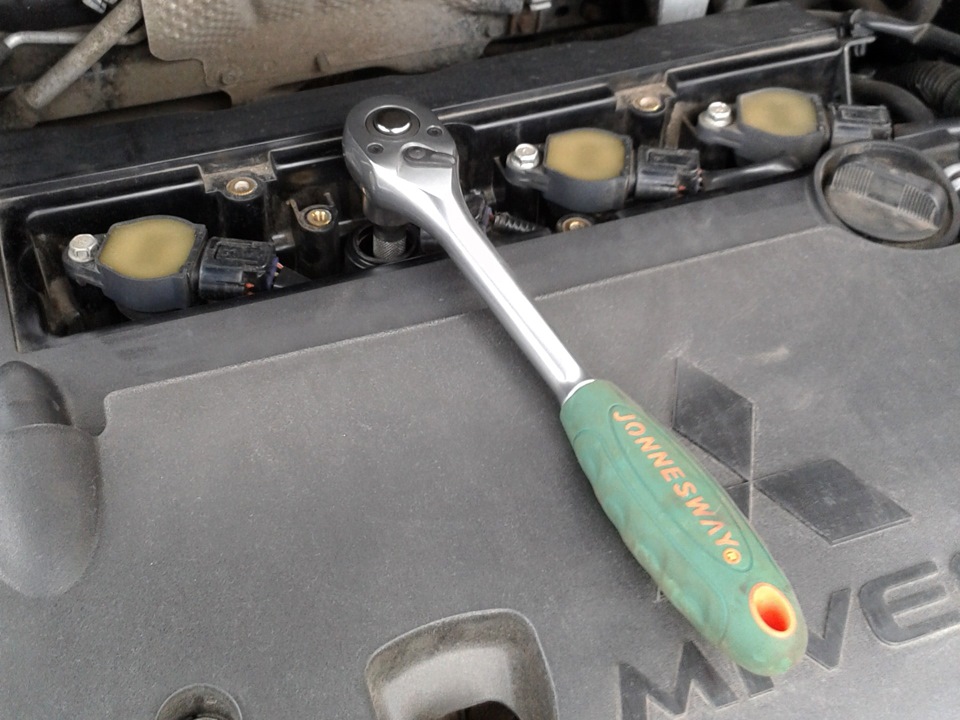
- Ключ трещоточный
- Удлинитель
- Головка на 10 мм
- Свечной ключ (или высокая головка на 16 мм)
- Компрессометр
- Шприц (при необходимости)
- Компрессор (при необходимости)
Инструменты (для двигателя 6B31):
- Гаечный ключ рожковый на 8 мм
- Гаечный ключ рожковый на 10 мм
- Ключ трещоточный
- Удлинитель
- Головка на 10 мм
- Головка на 12 мм
- Отвертка плоская средняя
- Отвертка крестовая средняя
- Круглогубцы изогнутые
- Плоскогубцы
- Нож (или скребок)
- Динамометрический ключ
- Свечной ключ (или высокая головка на 16 мм)
- Компрессометр
- Шприц (при необходимости)
- Компрессор (при необходимости)
Детали и расходники:
- Уплотнительная прокладка верхней части впускного коллектора 1540A193 (для двигателя 6B31)
- Моторное масло (при необходимости)
- Шланг (при необходимости)
- Очиститель (или растворитель, для двигателя 6В31, при необходимости)
- Ветошь
Примечания:
Диагностика двигателей Мицубиси Аутлендер ХЛ без разборки осуществляется с помощью измерения компрессии. По ее среднему значению и по разнице значений в отдельных цилиндрах можно с достаточной точностью определить степень общего износа деталей цилиндро-поршневой группы двигателя, а также выяснить неисправности этой группы и деталей клапанного механизма.
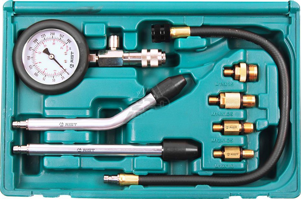
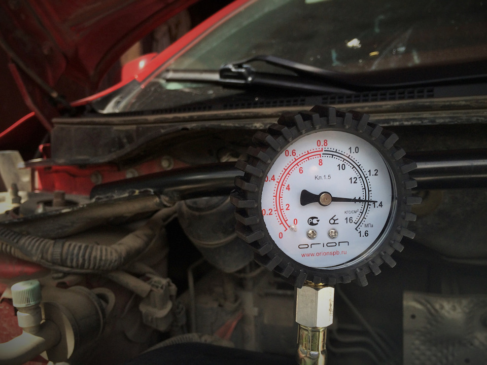
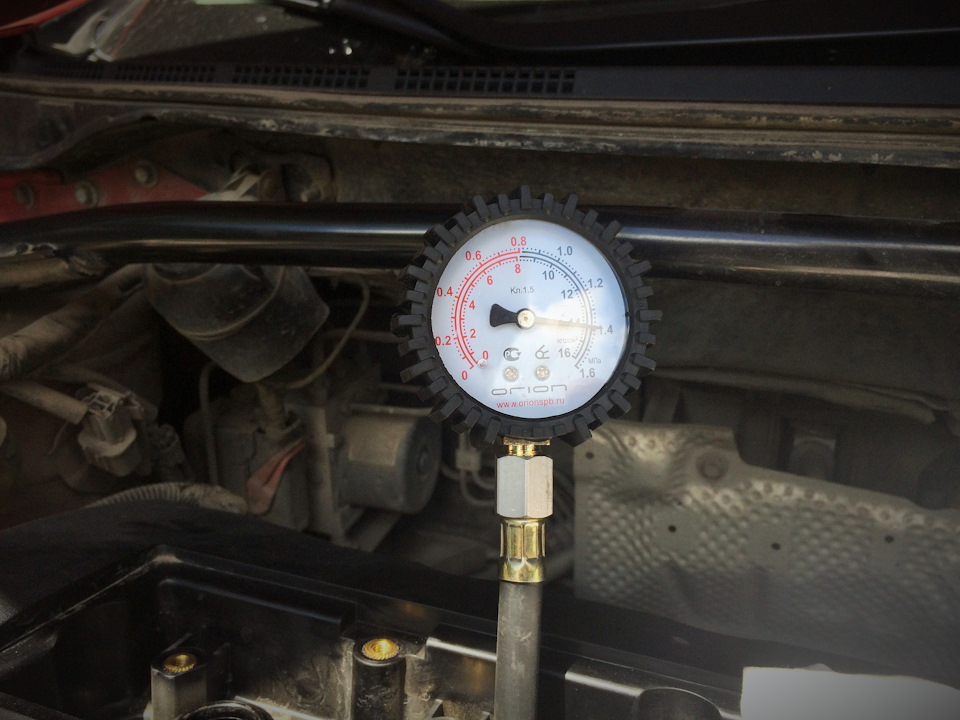
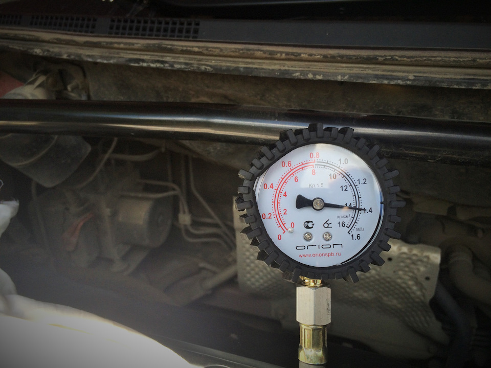
Замер компрессии в двигателе осуществляется специальным прибором – компрессометром. Они бывают немного разного исполнения. С резьбовым штуцером, который вкручивают в гнездо свечи зажигания. И компрессометры с резиновым наконечником, которые просто необходимо крепко вжимать в свечное отверстие.
Важными условиями правильности показаний при проверке компрессии являются исправность стартера и его электрических цепей, а также полная заряженность аккумуляторной батареи.
1. Пустите двигатель и прогрейте его до рабочей температуры.
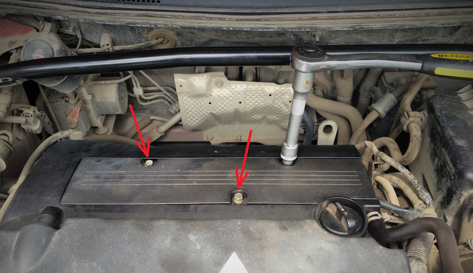
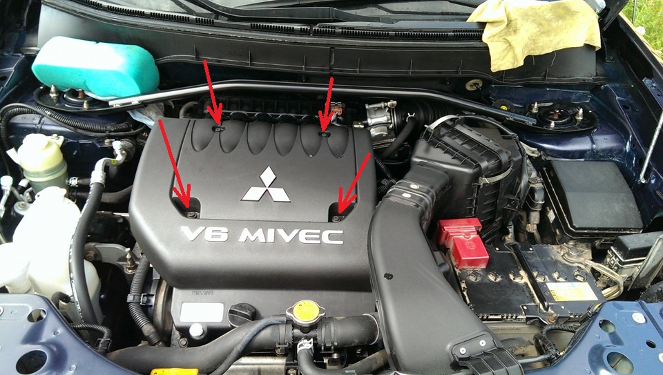
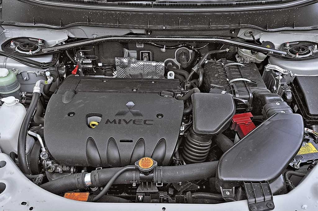
2.1. (двигатель 4B11/4B12) Откройте капот и отверните головкой на 10 мм три болта крепления пластины крышки головки блока цилиндров.
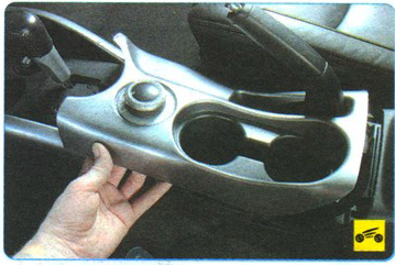
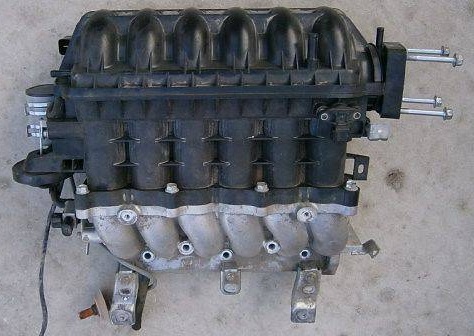
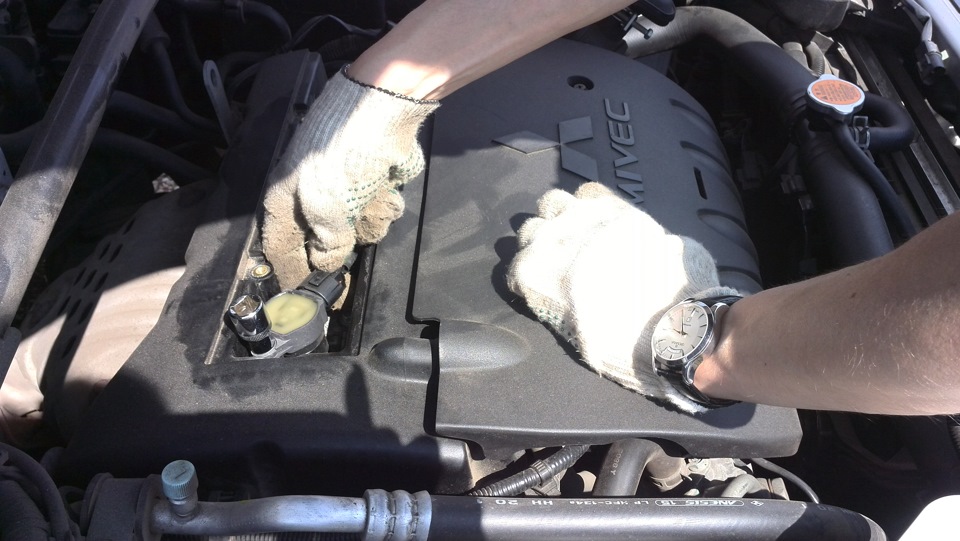
2.2. (двигатель 6В31) Снимите декоративный кожух двигателя и впускной коллектор.
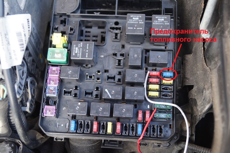
3. Снизьте давление в системе питания двигателя, как описано в этой статье.
4. Отсоедините колодки проводов от катушек зажигания.
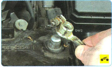
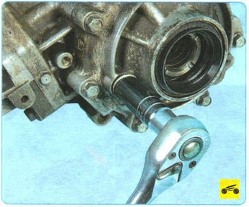
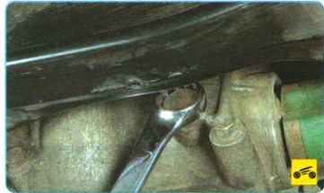
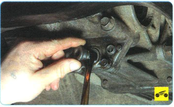
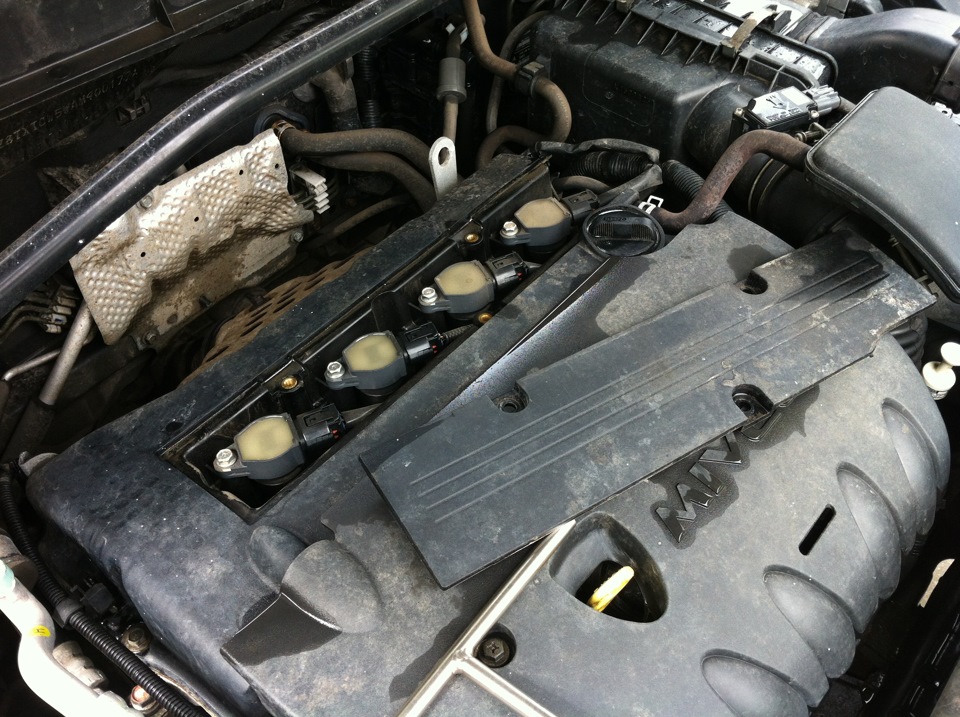
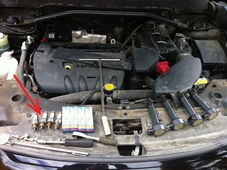
5. Головкой на 10 мм отверните болты крепления катушек зажигания (первых два фото – двигатель 4B12; третье фото – двигатель 6B31).
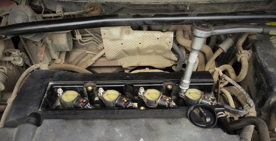
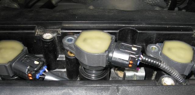
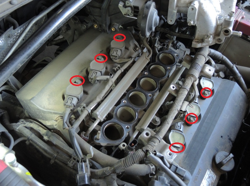
6. Выньте катушки зажигания из свечных колодцев, потянув их вверх.
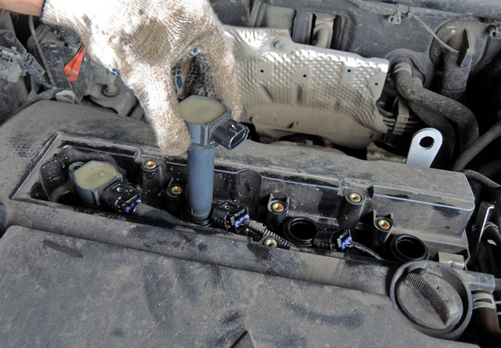
Примечание:
Будьте в обращении с катушками крайне осторожными. Даже малейший удар по ним может привести к их выходу из строя.
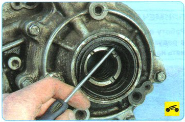
7. Выверните свечу зажигания и извлеките ее из свечного колодца.
8. Вверните компрессометр в свечное отверстие проверяемого цилиндра.
9. Нажмите на педаль акселератора до упора, чтобы при проворачивании коленчатого вала стартером дроссельная заслонка полностью открылась в режиме продувки цилиндров двигателя.
10. Включите стартер и проворачивайте им коленчатый вал двигателя до тех пор, пока давление в цилиндре не перестанет увеличиваться. Это соответствует примерно четырем тактам сжатия.
Примечание:
Для получения правильных показаний компрессометра коленчатый вал должен вращаться с частотой 180-200/мин. или выше, но не более 350/мин.
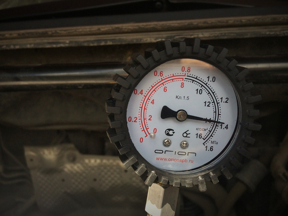
11. Запишите показания компрессометра и установите его стрелку на ноль, нажав на клапан выпуска воздуха.
Примечание:
У компрессометров иной конструкции показания могут сбрасываться другими способами (в соответствии с инструкцией к прибору).
12. Повторите операции 8-11 для остальных цилиндров. Давление должно быть не ниже 1,0 МПа и не должно отличаться в разных цилиндрах более чем на 0,1 МПа.
Примечание:
Низкая компрессия в одном цилиндре может возникнуть в результате неплотной посадки клапанов в седлах, повреждения прокладки головки блока цилиндров, поломки или пригорания поршневых колец. Пониженная компрессия во всех цилиндрах указывает на износ поршневых колец.
13. Для выяснения причин недостаточной компрессии залейте шприцом со шлангом в цилиндр с пониженной компрессией около 20 мл чистого моторного масла и вновь измерьте компрессию.
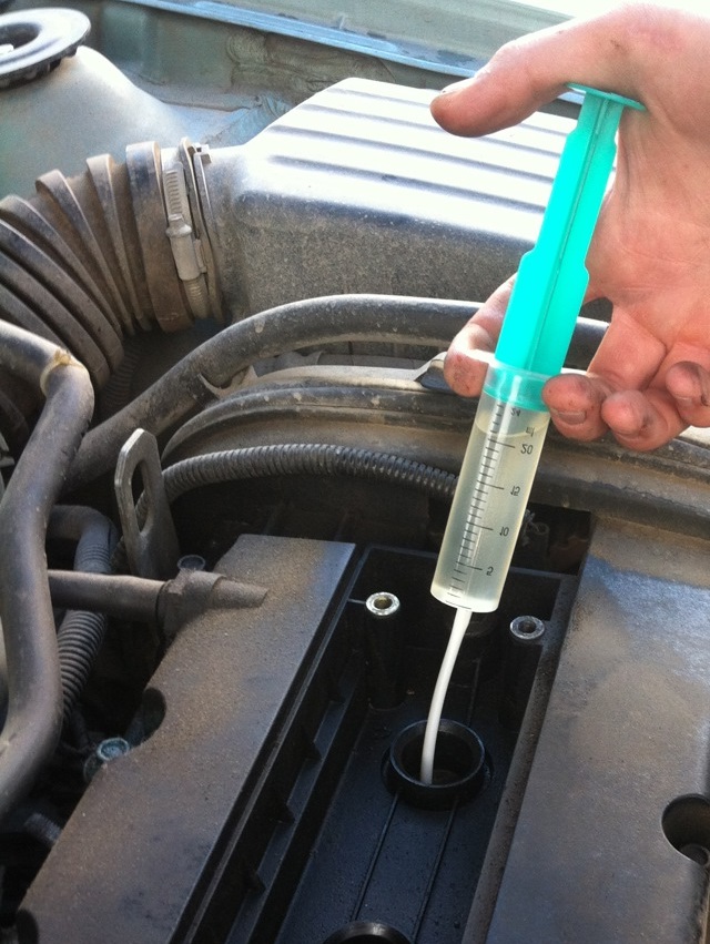
Примечание:
Если показания компрессометра повысились, наиболее вероятна неисправность поршневых колец. Если компрессия осталась неизменной, значит, тарелки клапанов неплотно прилегают к их седлам или повреждена прокладка головки блока цилиндров.
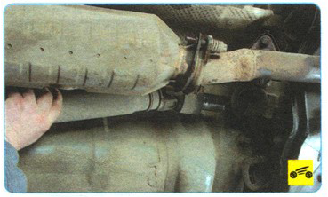
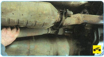
Причину недостаточной компрессии можно выяснить также подачей сжатого воздуха в цилиндр, в котором поршень предварительно установлен в ВМТ такта сжатия. Для этого снимите с компрессометра наконечник и присоедините к нему шланг компрессора. Вставьте наконечник в свечное отверстие и подайте в цилиндр воздух под давлением 0,2-0,3 МПа. Для того чтобы коленчатый вал двигателя не провернулся, включите высшую передачу и затормозите автомобиль стояночным тормозом. Выход (утечка) воздуха через дроссельный узел свидетельствует о негерметичности впускного клапана, а через глушитель о негерметичности выпускного клапана. При повреждении прокладки головки блока цилиндров воздух будет выходить через горловину расширительного бачка в виде пузырей.
14. После проверки компрессии установите все снятые детали в обратном порядке.
В статье не хватает:
- Фото инструмента
Источник: carpedia.club