Note:
Hyundai wiring diagrams are described in this article:
- Engine control system.
- Engine control system.
- Engine control system.
- Engine control system.
- Engine start system without electronic key.
- Engine start system with electronic key.
- Cooling system.
- Charging system without AMS.
- Charging system with AMS.
- Body electrical control module.
- Immobilizer.
- Rear fog light.
- Front fog lights.
- Headlight electric corrector.
- Door lock drive with BCM.
- Door lock actuator without BCM.
- Side lights and license plate lighting.
- Block headlight.
- Reverse light.
- ABS system.
- Brake lights for vehicles without ABS.
- Audio system.
- Audio system.
- Windshield wipers and windshield washer.
- Driver's door power window (with intelligent drive module).
- Front passenger door power window (with intelligent drive module).
- Rear power windows (with intelligent drive module).
- Driver's door power window (no smart power window module).
- Power windows for front passenger and rear doors (without intelligent power window drive module).
- Sound signal.
1. Scheme of the engine control system.
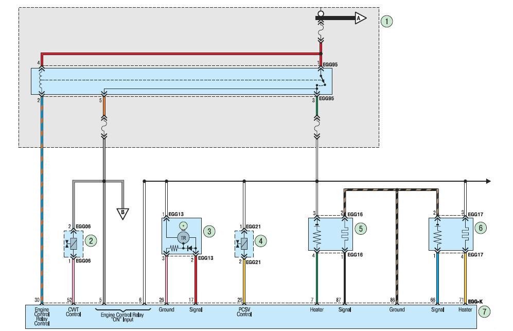
Engine management system:
1 - mounting block in the engine compartment;
2 - solenoid valve (EMC) of the variable valve timing system (CVVT);
3 - camshaft position sensor;
4 – EMC of the fuel vapor recovery system;
5 – control oxygen concentration sensor;
6 – diagnostic oxygen concentration sensor;
7 - electronic engine control unit.
2. Scheme of the engine control system.
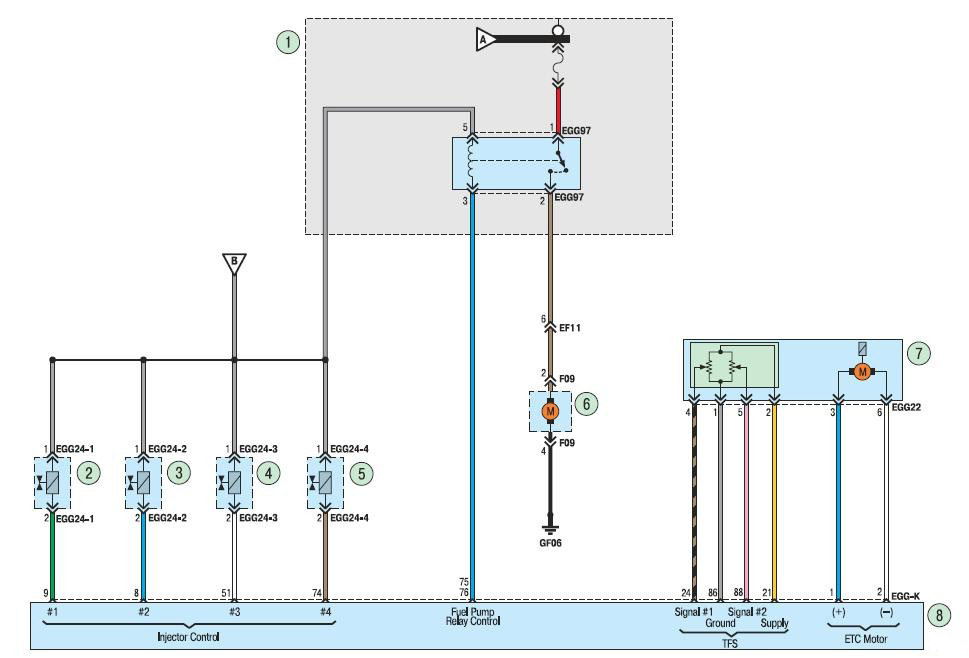
Engine management system:
1 - mounting block in the engine compartment;
2, 3, 4, 5 - nozzles;
6 – fuel level sensor and fuel module;
7 - throttle assembly;
8 - electronic engine control unit.
3. Scheme of the engine control system.
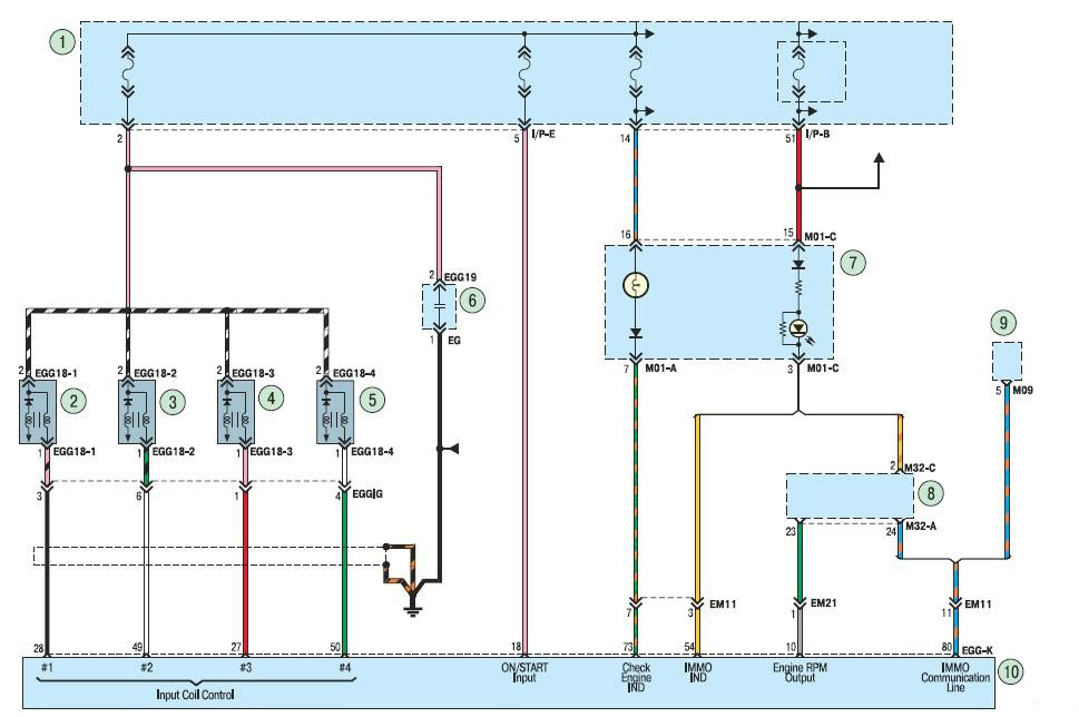
Engine management system:
1 - mounting block in the engine compartment;
2, 3, 4, 5 - ignition coils;
6 - capacitor;
7 – a combination of devices;
8 - electronic ignition key;
9 - immobilizer module;
10 - electronic engine control unit.
4. Scheme of the engine control system.
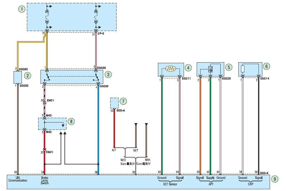
Engine management system:
1 - mounting block in the car;
2 – generator control system (AMS);
3 – stoplight switch;
4 - coolant temperature sensor;
5 - pressure sensor in the air conditioning system;
6 - crankshaft position sensor;
7 - transmission control module;
8 - brake light relay;
9 - electronic engine control unit.
5. Wiring diagram of the Hyundai Solaris engine start system without an electronic key.
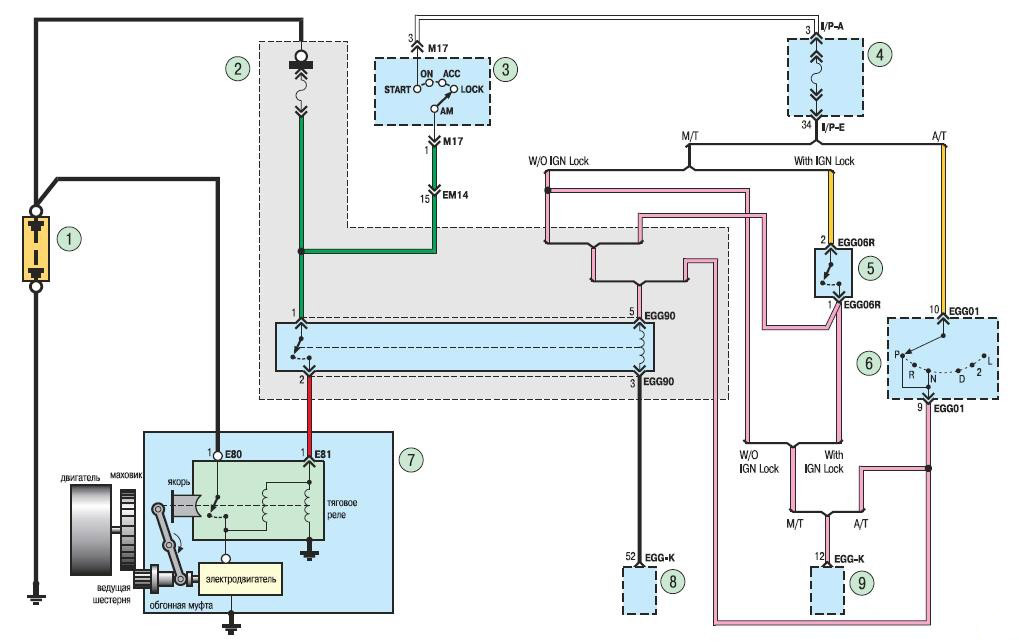
Engine start system without electronic key:
1 - rechargeable battery;
2 - mounting block in the engine compartment;
3 - ignition switch (lock);
4 - mounting block in the car;
5 - ignition control module;
6 – the selector of an automatic transmission;
7 - starter;
8, 9 - electronic engine control unit.
6. Wiring diagram of the engine start system with an electronic key.
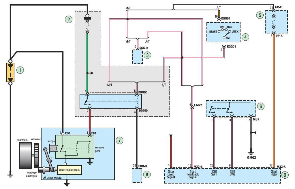
Engine start system with electronic key:
1 - rechargeable battery;
2 - mounting block in the engine compartment;
3 - electronic engine control unit;
4 – the selector of an automatic transmission;
5 - mounting block in the car;
6 - button to start and stop the engine;
7 - starter;
8 - electronic engine control unit;
9 - control module for the engine start and stop button.
7. Scheme of electrical equipment of the Hyundai cooling system.
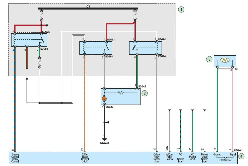
Cooling system:
1 - mounting block in the engine compartment;
2 - electric fan of the engine cooling system;
3 - coolant temperature sensor;
4 - electronic engine control unit.
8. Wiring diagram of the charging system without AMS.
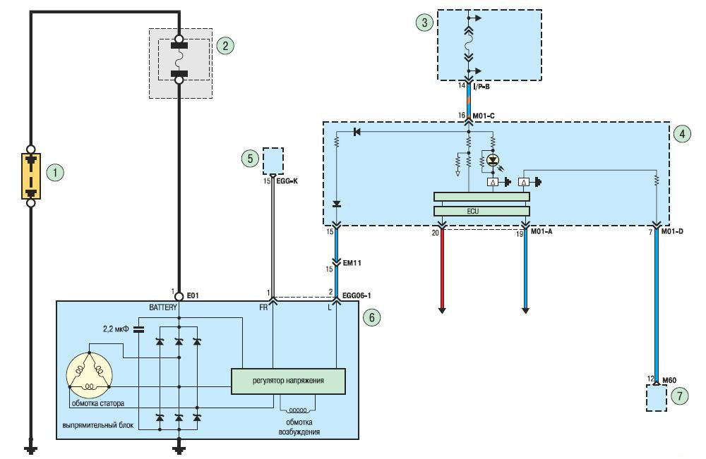
Wiring Hyundai charging system without AMS:
1 - rechargeable battery;
2 - mounting block in the engine compartment;
3 - mounting block in the car;
4 – a combination of devices;
5 - electronic engine control unit;
6 - generator;
7 - airbag control module.
9. Wiring diagram of the charging system with AMS.
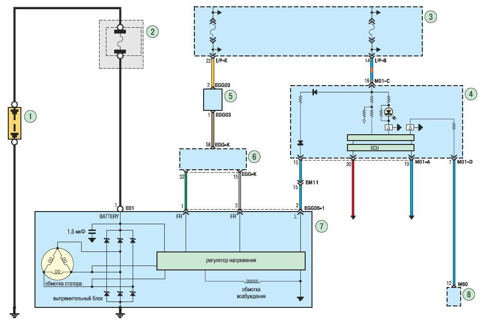
Charging system with AMS:
1 - rechargeable battery;
2 - mounting block in the engine compartment;
3 - mounting block in the car;
4 – a combination of devices;
5 – generator control system (AMS);
6 - electronic engine control unit;
7 - generator;
8 - airbag control module.
10. Wiring diagram of the body electrical control module.
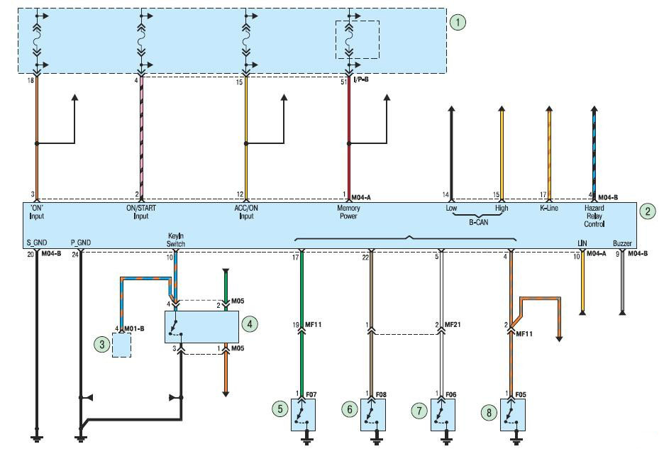
Body electrical control module:
1 - mounting block in the car;
2 - body electrical control module;
3 – a combination of devices;
4 - annunciator of open doors;
5 – the limit switch of the left back door;
6 – the limit switch of the right back door;
7 – the limit switch of a passenger door;
8 - the limit switch of a door of the driver.
11. Wiring diagram of the immobilizer system.
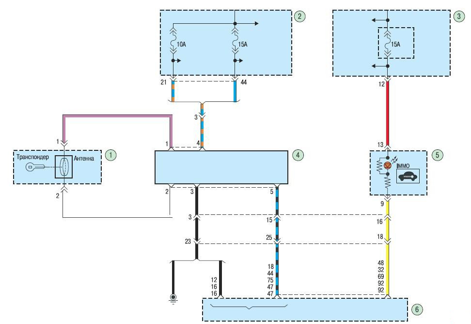
Immobilizer:
1 - antenna block of the immobilizer;
2 - relay and fuse block in the engine compartment;
3 - block of relays and fuses in the passenger compartment;
4 - immobilizer module;
5 – a combination of devices;
6 - electronic engine control unit.
12. Wiring diagram of the rear fog light system.
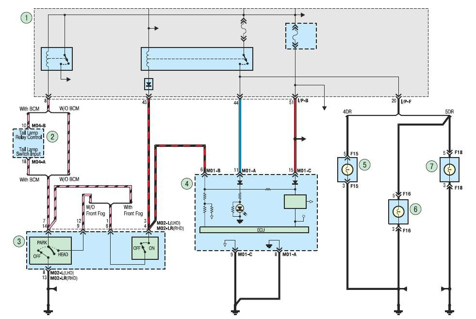
Rear fog light:
1 - mounting block in the car;
2 - control module for body electrical equipment;
3 - switch for outdoor lighting and direction indicators;
4 – a combination of devices;
5, 6 - left rear lights;
7 - right rear light.
13. Wiring diagram of the front fog lights.
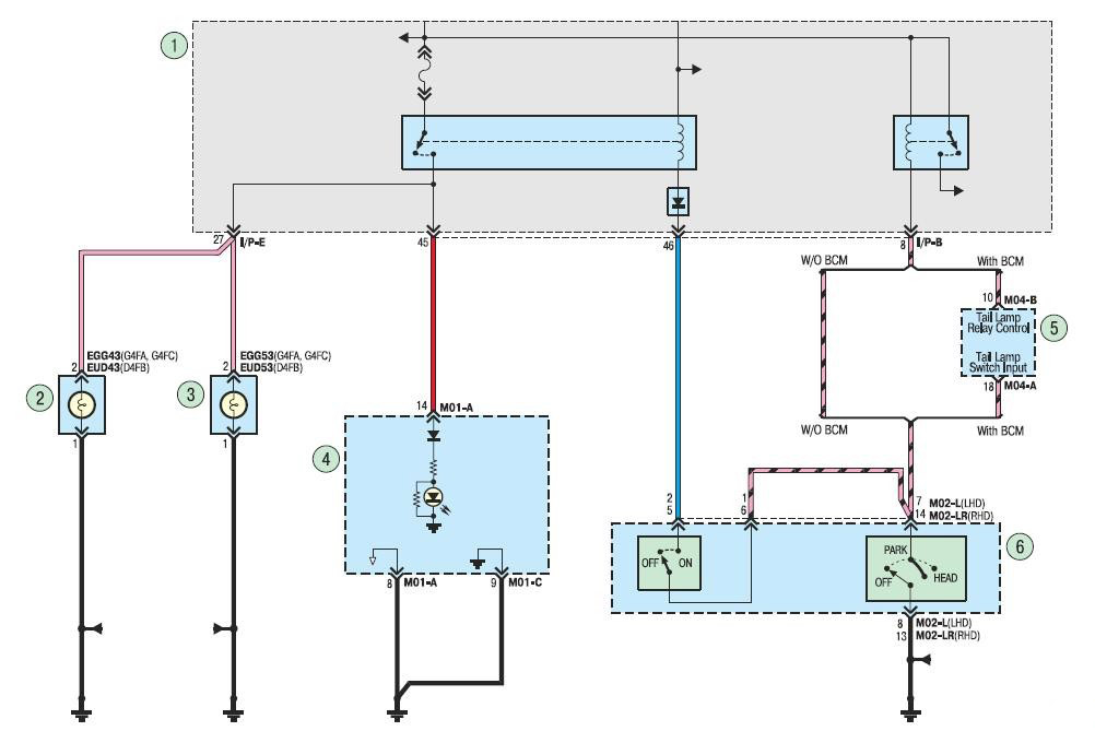
Front fog lights:
1 - mounting block in the car;
2 - left front fog lamp;
3 - right front fog lamp;
4 – a combination of devices;
5 - body electrical control module;
6 - switch for outdoor lighting and direction indicators.
14. Wiring diagram of the electric corrector for headlights.
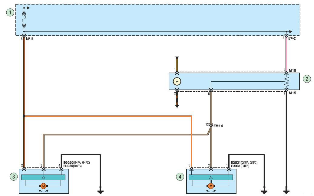
Headlight electric corrector:
1 - mounting block in the car;
2 - headlight electrocorrector regulator;
3 - left electric corrector;
4 - right electric corrector.
15. Wiring diagram of the door lock drive with the BCM block.
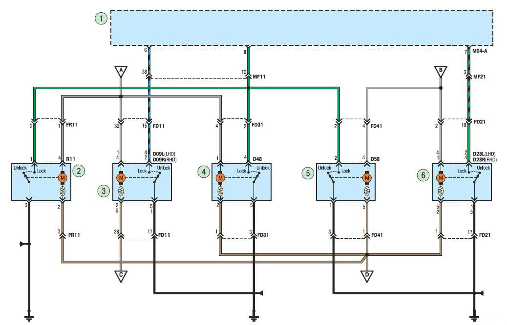
Door lock actuator with BCM:
1 - body electrical control module;
2 – tailgate lock drive;
3 – a drive of the lock of a door of the driver;
4 – a drive of the lock of the left back door;
5 – a drive of the lock of the right back door;
6 - front passenger door lock drive.
16. Wiring diagram for door locks without BCM.
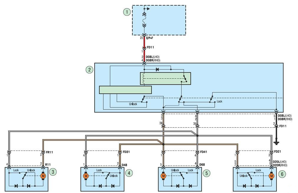
Door lock actuator without BCM:
1 - mounting block in the car;
2 – a drive of the lock of a door of the driver;
3 – tailgate lock drive;
4 – a drive of the lock of the left back door;
5 – a drive of the lock of the right back door;
6 - front passenger door lock drive.
17. Wiring diagram for parking lights and license plate lighting.
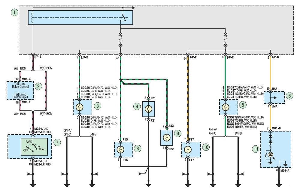
Parking lights and license plate lighting:
1 - mounting block in the car;
2 - body electrical control module;
3 – a lamp of dimensional fire of the left headlight;
4 – the left lamp of illumination of license plate;
5 – a lamp of dimensional fire of the right headlight;
6 - connecting block;
7 - stalk switch for outdoor lighting and direction indicators;
8 – a lamp of dimensional fire of the left back lantern;
9 – the right lamp of illumination of license plate;
10 – a lamp of dimensional fire of the right back lantern;
11 - a combination of devices.
18. Wiring diagram of the headlight.
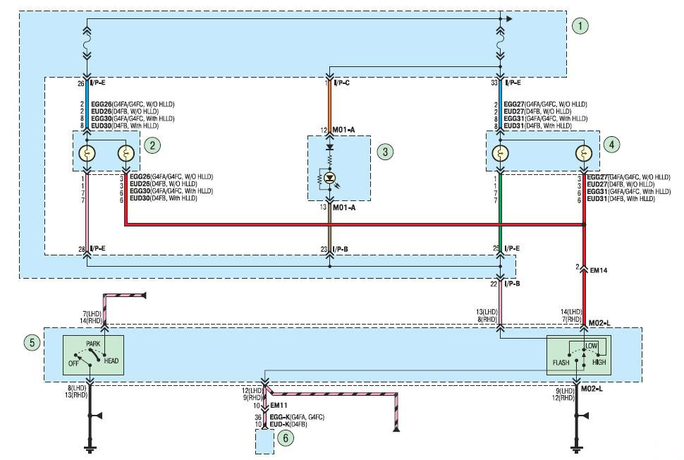
Block headlight:
1 - mounting block in the car;
2 - low and high beam lamps of the left headlight;
3 – a combination of devices;
4 - low and high beam lamps of the right headlight;
5 - stalk switch for outdoor lighting and direction indicators;
6 - electronic engine control unit.
19. Wiring diagram for reversing light.
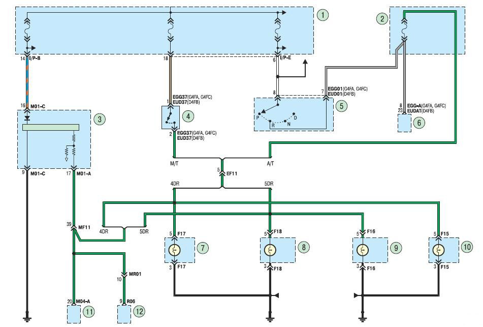
Reversing light:
1 - mounting block in the car;
2 - mounting block in the engine compartment;
3 – a combination of devices;
4 - reverse light switch;
5 – the selector of an automatic transmission;
6 - transmission control module;
7, 8 – a lamp of dimensional light of the right back lantern;
9, 10 – marker lamp of the left rear lamp;
11 - body electrical control module;
12 - a rear-view mirror with an automatic dimming function.
20. Wiring diagram of the ABS system.
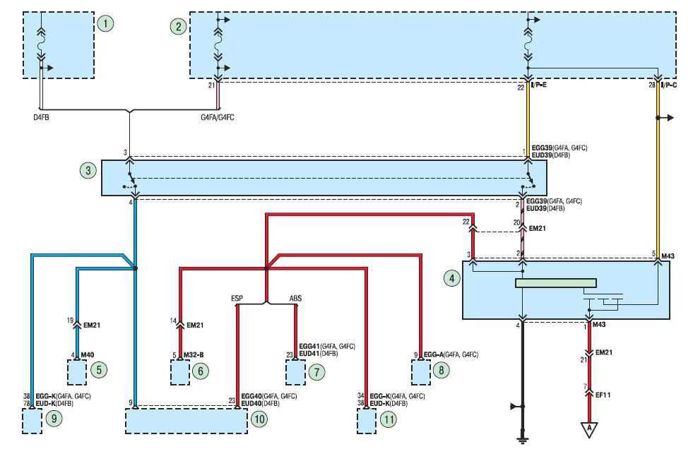
ABS system:
1 - mounting block in the engine compartment;
2 - mounting block in the car;
3 – stoplight switch;
4 – the relay of lamps of a stoplight;
5 - control module for turning on the steering lock;
6 - electronic ignition key;
7 – ABS hydroelectronic module;
8 - transmission control module;
9, 11 - electronic engine control unit;
10 - ESP system control module.
21. Wiring diagram of a brake light for a car without an ABS system.
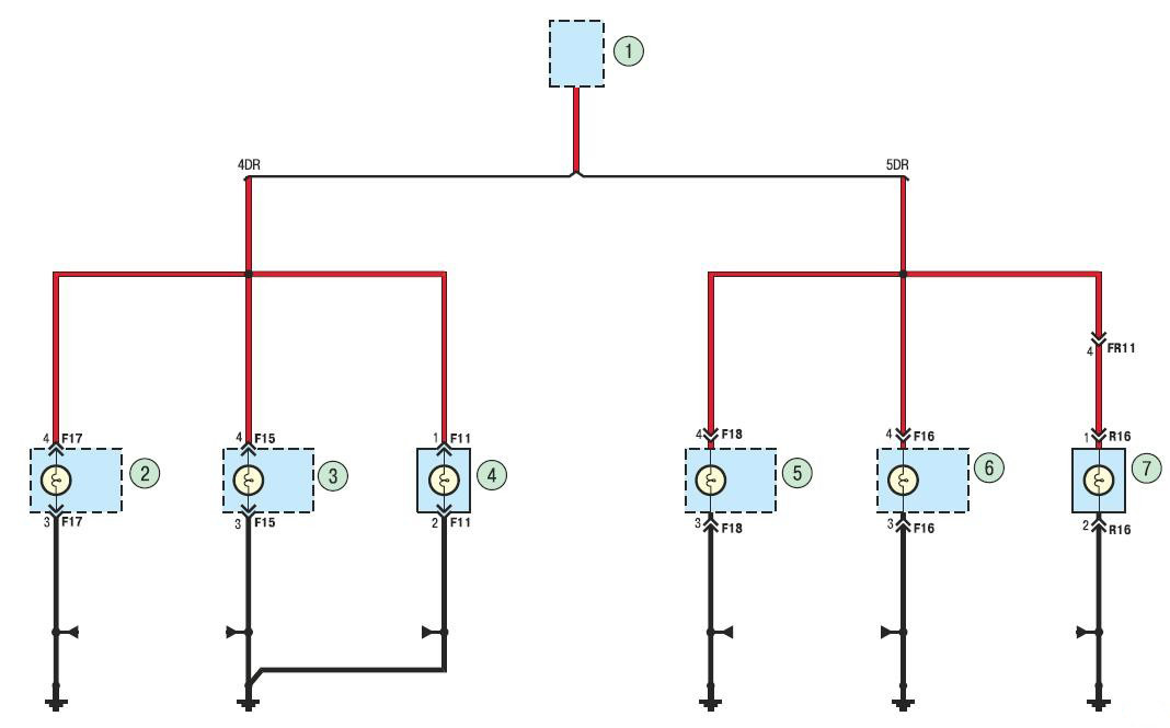
Brake lights for vehicles without ABS:
1 – the relay of lamps of a stoplight;
2, 5 - right rear light;
3, 6 - left rear light;
4, 7 - additional brake light.
22. Wiring diagram of the audio system.
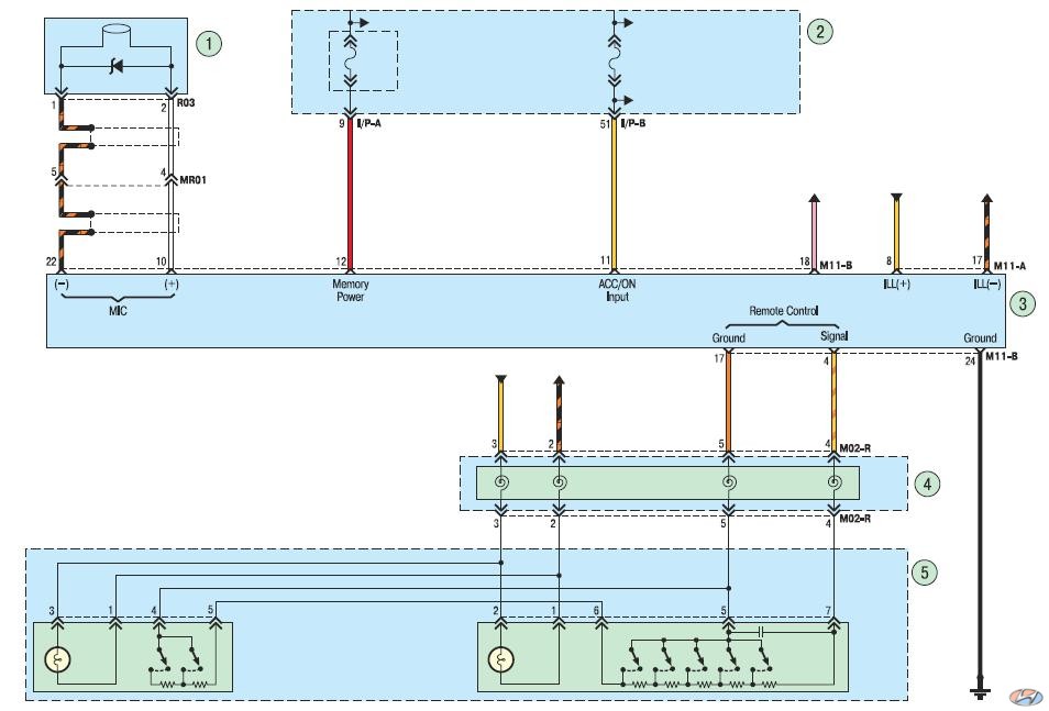
Audio system:
1 - microphone;
2 - mounting block in the car;
3 - the head unit of the audio system;
4 - contact ring;
5 - audio control unit on the steering wheel.
23. Wiring diagram of the audio system.
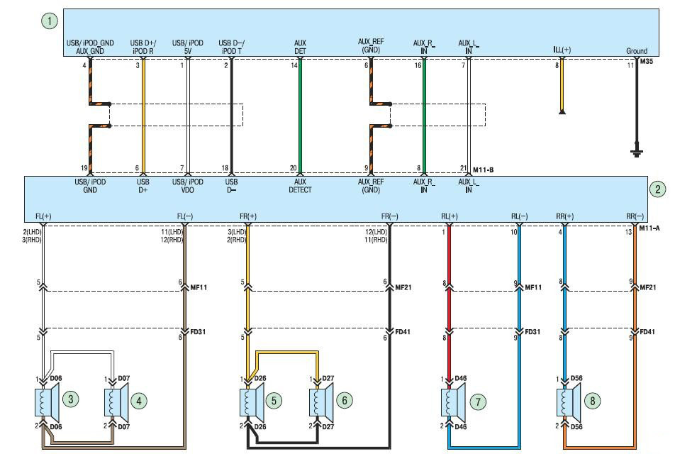
Audio system:
1 - block for connecting multimedia devices;
2 - the head unit of the audio system;
3 – the loudspeaker located in an upholstery of a door of the driver;
4 - left front high-frequency speaker;
5 – the loudspeaker located in an upholstery of a door of the forward passenger;
6 - right front high-frequency speaker;
7 – the loudspeaker located in an upholstery of the left back door;
8 - a speaker located in the upholstery of the right rear door.
24. Wiring diagram for windshield wipers and windshield washers.
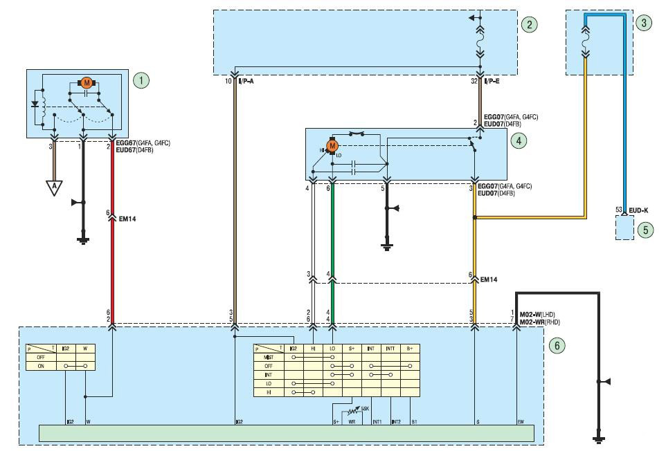
Windshield wipers and windshield washer:
1 – washer electric pump;
2 - mounting block in the car;
3 - mounting block in the engine compartment;
4 - front wiper motor reducer;
5 - electronic engine control unit;
6 - switch for the windshield wiper and washer.
25. Wiring diagram for the power window of the driver's door (with an intelligent drive module).
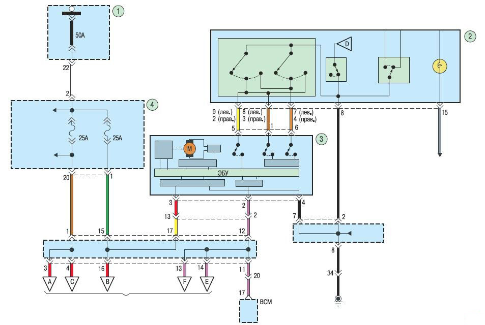
Driver's door power window (with intelligent drive module):
1 - relay and fuse block in the engine compartment;
2 - control unit for power windows, rear-view mirrors and blocking door locks (with an intelligent power window drive module);
3 - an intelligent power window drive module of the driver's door;
4 - a block of relays and fuses in the passenger compartment.
26. Wiring diagram for the power window of the front passenger door (with an intelligent drive module).
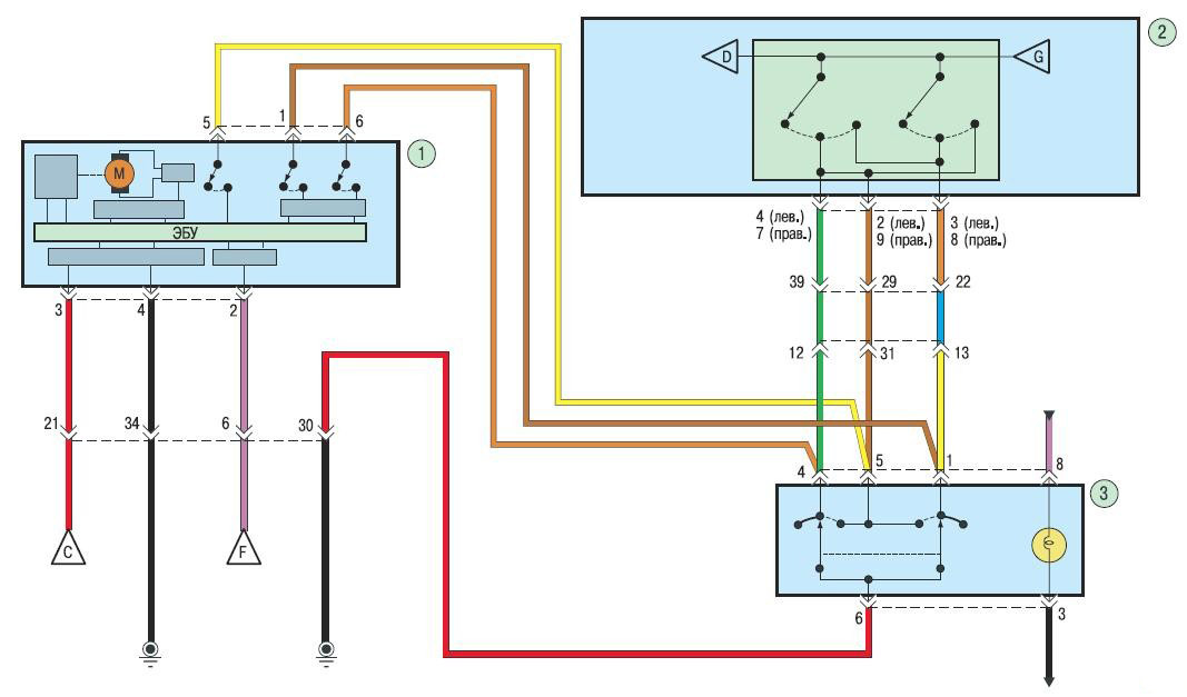
Front Passenger Power Window (with Intelligent Drive Module):
1 - an intelligent power window drive module for the front passenger door;
2 - control unit for power windows, rear-view mirrors and blocking door locks (with an intelligent power window drive module);
3 - power window control key for the front passenger door.
27. Wiring diagrams for power windows of the rear doors (with an intelligent drive module).
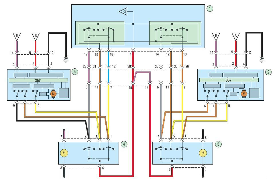
Rear power windows (with intelligent drive module):
1 - control unit for power windows, rear-view mirrors and blocking door locks (with an intelligent power window drive module);
2 - an intelligent power window drive module of the right rear door;
3 – a key of management of an electrowindow regulator of the right back door;
4 – a key of management of an electrowindow regulator of the left back door;
5 - an intelligent power window drive module for the left rear door.
28. Wiring diagram for the power window of the driver's door (without an intelligent power window drive module).
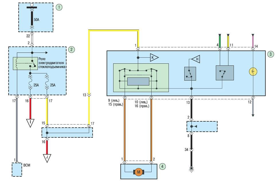
Driver's door power window (without intelligent power window module):
1 - relay and fuse block in the engine compartment;
2 - block of relays and fuses in the passenger compartment;
3 - control unit for power windows, rear-view mirrors and blocking door locks;
4 – the electric motor of a window lifter of a door of the driver.
29. Wiring diagram for the power window of the front passenger and rear doors (without an intelligent power window drive module).
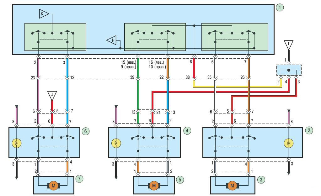
Power windows front passenger and rear doors (without intelligent window drive module):
1 - control unit for power windows, rear-view mirrors and blocking door locks;
2 – a key of management of an electrowindow regulator of the right back door;
3 – the electric motor of a window regulator of the right back door;
4 - control key for the power window of the front passenger door; 5 – the electric motor of a window regulator of a forward passenger door;
6 - power window control key of the left rear door;
7 – the electric motor of a window regulator of a forward passenger door.
30. The electrical circuit of the sound signal.
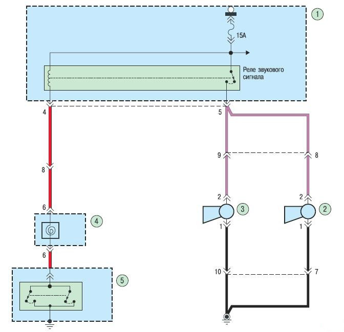
Sound signal:
1 - relay and fuse block in the engine compartment;
2 – high tone signal;
3 – low tone signal;
4 – contact ring of an airbag;
5 - key for turning on the sound signal.
Source: http://carpedia.club/
![1 generation [2010 - 2014]](/uploads/Hyundai_Solaris_2010_-_2014_.jpg)
