![1 generation [2009 - 2014]](/uploads/Renault_Sandero_2009-2014_.jpg)

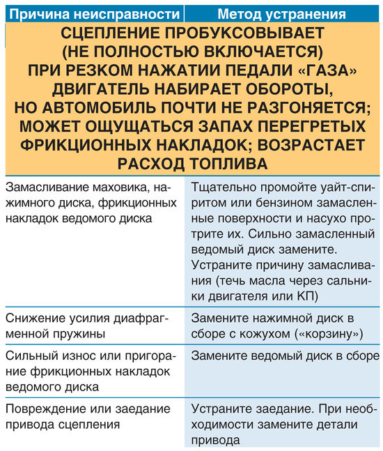
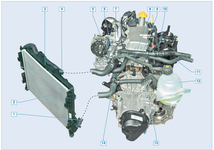
Engine cooling system:
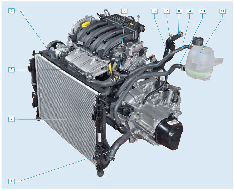
1 - outlet hose of the radiator;
2 - radiator;
3 - fan casing;
4 – a bringing hose of a radiator;
5 - thermostat housing;
6 - outlet hose of the heater radiator;
7 - air outlet fitting;
8 - inlet hose of the heater radiator;
9 - steam outlet hose;
10 - inlet hose;
11 - expansion tank
Cooling system - liquid, closed type, with forced circulation. It consists of an expansion tank, a coolant pump, an engine cooling jacket, a thermostat, connecting hoses and a radiator with an electric fan. The heater core is connected to the cooling system.
The system is filled with coolant through the neck of the expansion tank.
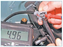
Expansion tank elements:
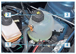
1 - steam outlet hose;
2 – a cover of a jellied mouth;
3 - tank;
4 - inlet hose
The expansion tank is made of translucent plastic, which allows you to visually control the level of the coolant. On the wall of the expansion tank there are marks MAX and MIN, between which there should be a liquid level on a cold engine. A steam outlet hose is connected to the top fitting of the tank, connecting the tank to the thermostat cover. The inlet hose of the expansion tank and the outlet hose of the radiator are connected to the inlet pipe of the pump
Expansion tank cap
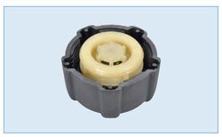
The tightness of the cooling system is ensured by inlet and outlet valves in the cap of the expansion tank.
The exhaust valve maintains a higher than atmospheric pressure in the system on a hot engine. This increases the boiling point of the liquid and reduces steam losses. The intake valve opens when the pressure in the system drops when the engine is cold.
Warning: If the cover is lost, it cannot be replaced with a sealed cover without valves, even of a suitable size and thread - this will lead to an unacceptable increase in pressure in the cooling system (on a hot engine) and, as a result, leakage of coolant from under the hose clamps.
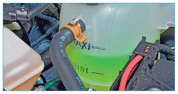
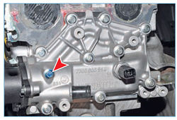
The union for release of air from the cooling system
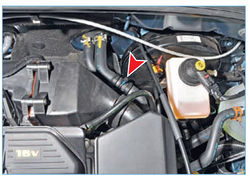
There is a fitting on the hose for supplying fluid to the heater, and on the thermostat housing there is a plug for venting air from the cooling system when it is filled with liquid. The fitting on the hose is closed with a cap.
Coolant pump:
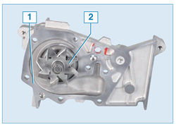
1 - body;
2 - impeller
The circulation of liquid in the cooling system is provided by the coolant pump. The coolant pump is a vane, centrifugal type, driven by a timing belt from the crankshaft toothed pulley. It consists of a housing, a bearing assembly with a seal, an impeller and a toothed pulley. The liquid enters the pump through a supply pipe located on the front wall of the cylinder block under the protection of the fuel rail.
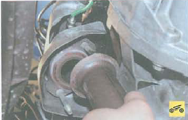
Thermostat:
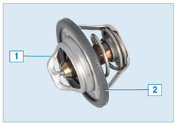
1 - thermostat;
2 - O-ring
From the pump, liquid under pressure is supplied to the engine cooling jacket, and from there to the thermostat housing.
The thermostat contributes to the acceleration of engine warm-up, automatic maintenance of its thermal conditions within the specified limits and regulates the amount of fluid passing through the radiator. Inside the thermostat there is a metal cylinder with a thermosensitive filler (wax). The balloon is hermetically sealed with a rubber insert. When heated, the filler melts and increases its volume, squeezing the insert.
The rubber insert is deformed, while the membrane bends and moves the stem that controls the thermostat valve.
On a cold engine, the thermostat valve is closed and closes the pipe leading to the radiator of the cooling system. In this case, all the liquid through the thermostat housing enters the heater radiator, bypassing the cooling system radiator, and returns to the pump - a small circulation circle. As the engine warms up, at a fluid temperature of 89 ° C, the thermostat valve begins to move, allowing fluid to flow into the radiator of the cooling system. At a temperature of 95 ± 2 ° C, the thermostat valve opens completely and the liquid enters the radiator of the cooling system, where it gives off heat to the surrounding air.
Plug on the thermostat housing to bleed air from the cooling system
The movement of fluid through the engine cooling jacket and the cooling system radiator forms a large circulation circle. The liquid circulates through the heater radiator constantly and does not depend on the position of the thermostat valve.
Radiator:
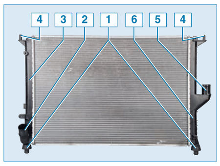
1 - rubber cushion of the lower mount;
2 - outlet pipe;
3 - left tank;
4 – top fastening pin;
5 - inlet pipe;
6 - right tank The
radiator of the cooling system consists of two vertically located plastic tanks connected by aluminum tubes with cooling plates. The liquid enters the radiator through the pipe in the right tank, and is discharged through the pipe in the left tank. The radiator does not have a drain hole.
Cooling fan assembly with radiator:
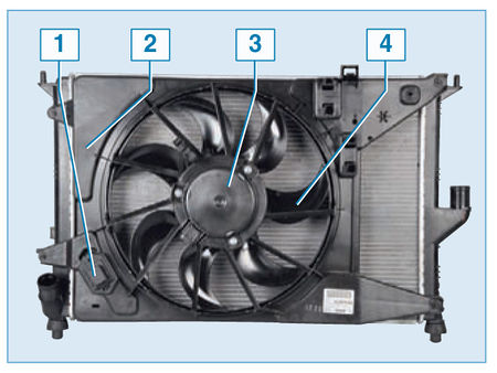
1 - additional resistor;
2 - casing;
3 - electric motor;
4 - impeller
The electric fan is installed in the casing behind the radiator.
With an increase in the temperature of the coolant, the fan turns on at the command of the electronic control unit (ECU) of the engine through a relay.
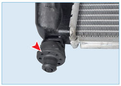
Rubber cushion lower radiator mount
Additional fan resistor
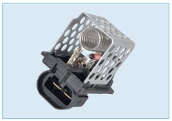
On vehicles equipped with air conditioning, an additional resistor is installed on the fan shroud. When the coolant temperature rises or when the air conditioner is turned on, the computer turns on the fan through an additional resistor and the fan rotates at low speed. With a further increase in the temperature of the liquid and the achievement of a refrigerant pressure value above the threshold level, the ECU turns on the electric motor, bypassing the resistor, and the fan rotates at high speed.
The fan will turn on at low speed when the coolant temperature rises above 99°C and turn off when the temperature drops to 96°C.
The fan will turn on at high speed when the coolant temperature rises above 102°C and turn off when the temperature drops to 98°C.
If the coolant temperature exceeds 118 ° C, the engine overheat warning lamp lights up in the instrument cluster.
If the coolant temperature exceeds 103 °C after the ignition is switched off, the fan continues to run at low speed for five minutes. Once the liquid temperature drops below 100 °C, the fan is switched off.
coolant temperature sensor
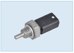
The coolant temperature sensor is screwed into the thermostat housing.
The sensor provides information to the temperature gauge in the instrument cluster, the engine overheating indicator and the electronic unit of the engine management system.
Source: http://wiki.zr.ru/171-2_%D0%A0%D0%B5%D0%BC%D0%BE%D0%BD%D1%82_Stepway