![3 generation [2012 - 2017]](/uploads/Skoda_Rapid_2012_-_2016.png)

Tool:
- Set of wrenches
Note:
During any assembly work, especially in the engine compartment due to the narrow assembly area, the following guidelines must be observed
: to restore them to their original state.
Ensure that there is sufficient space between the piping and moving or hot components to avoid damaging the piping.
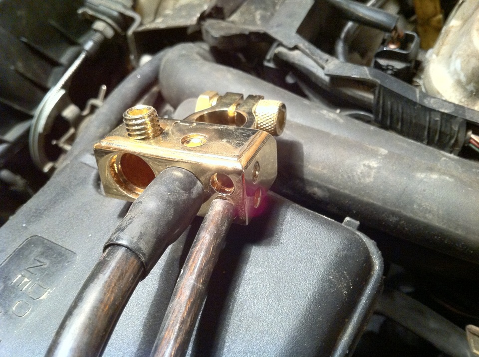
1. With the ignition off, disconnect the negative terminal from the battery.
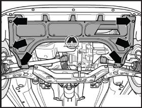
2. Remove the lower protective casing of the engine compartment (arrows).
3. Remove the mounting bolts and disconnect the right and left drive shafts from the gearbox.
4. Raise the drive shafts and tie them down using a suitable piece of wire.
5. Remove the front of the exhaust pipe.
6. Drain the coolant into a prepared container.
7. Remove the battery and battery holder.
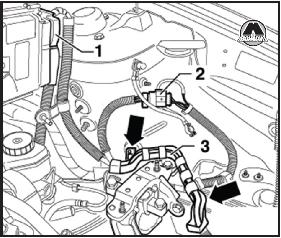
8. Disconnect the wiring harness connector (1) from the engine control unit.
9. Disconnect the wiring harness connector (2).
10. Release the wire holder (3) from the fixed position (arrows).
11. Disconnect all wires from the engine, transmission, starter and radiator that would interfere with removal.
12. Remove the intake hose from the vacuum brake booster.
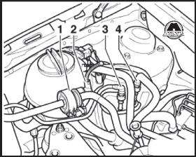
13. Having pressed the buttons of the clamps, disconnect the fuel supply (4) and drain (3) branch pipes of the power system.
14. Disconnect the wiring harness connector (2), then disconnect and remove the activated charcoal tank solenoid valve, fuel vapor recovery system (1).
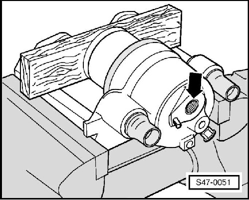
15. To remove a hose for removal of air from system of cooling from a forward tube for a cooling liquid.
16. To remove a water hose of system of cooling from a branch pipe under a broad tank of system of cooling.
17. Remove the counter support of the flexible shafts (Bowden cables).
18. Remove the hydraulic clutch release cylinder.
19. Disconnect the coolant hoses at the top and bottom on the connecting pipes from the radiator.
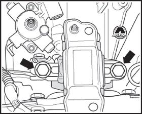
20. Unscrew the fastening bolts (arrows) and remove the oscillating support of the power unit.
For vehicles with air conditioning
Note:
Do not open the refrigerant circuit of the air conditioning system.
21. Remove the V-ribbed implement drive belt.
22. Disconnect the wiring harness connector from the A/C compressor.
23. Remove the A/C compressor with attached piping.
24. Suspend the air conditioning compressor from the vehicle in such a way that no collision occurs during the removal of the unit from the vehicle.
Note:
Do not bend the pipes of the air conditioning system connected to the compressor,
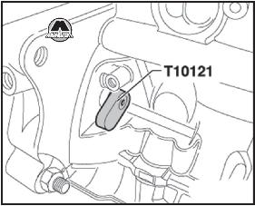
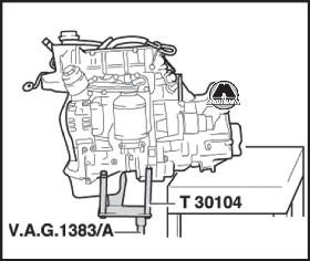
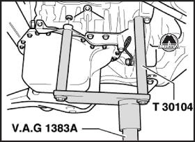
25. Install bracket for engine support -T30104- in tool for removing and installing power unit, eg -VAG 1383/A -.
26. Connect engine support bracket -T30104- with lock nuts and M8 screws applying a tightening torque of 30 N.m to the cylinder block.
Note:
Check that all hose and wire connections between the engine, gearbox and body are disconnected and, if necessary, disconnect them.
Use the ladder -V4S 5085- to remove the fixing bolts.
27. Slightly raise the engine with the gearbox using a device for removing and installing the power unit, e.g. -VAG 1383/ A-.
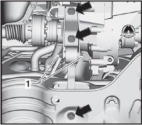
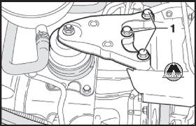
28. Unscrew the fastening screws (1).
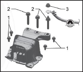
For vehicles with other support type
29. Unscrew the fastening nut (3) and disconnect the ground wire from the bracket.
30. Unscrew the bolts securing the bracket to the support of the power unit (2).
31. Unscrew the fixing screws (arrows) from the gearbox bearing.
32. Lower the engine with the gearbox down.
Note:
When lowering the engine with the gearbox, you need to do it carefully. It is necessary that there is always enough space in the surrounding area.
Mounting the engine on the assembly stand
33. Place the engine and gearbox with the tool for removal and installation to the table for putting things away.
34. Lower the engine with gearbox so that the gearbox rests on the table top.
35. Unscrew the bolts connecting the engine and gearbox.
36. Disconnect the gearbox from the engine.
37. Having hooked the suspension device (MP9-201 (2024 A)) in the following way, lift it from the support of the power unit with the help of a workshop crane.
38. To carry out assembly work, it is necessary to fix the engine with a device for removing and installing the engine and gearbox (MP1202) (using 3 bolts (arrows)) on the assembly stand -MP 9-101-.
39. Installation is carried out in the reverse order of removal.
Observe the following instructions:
1. Check the presence in the cylinder block of 2 centering bushes for centering the gearbox, if necessary, insert them.
2. If necessary, check the correct centering of the clutch disc.
3. Check the clutch release bearing for wear and, if necessary, replace the bearing.
4. Lubricate spline on drive shaft with grease -G 000 100-.
5. When assembling the engine-gearbox assembly, make sure that there is enough free space left in relation to the rest of the parts.
6. Center the engine with the gearbox in such a way that there are no internal stresses.
7. Install the clutch release hydraulic slave cylinder.
8. Connect the shift actuator and adjust the Bowden cables for shifting.
9. Install the air conditioning compressor.
The article is missing:
- Tool photo
- Photo of parts and consumables
- High-quality repair photos
Source: Manual for the repair and operation of Skoda Rapid, Monolit publishing house.