![1 generation [2011 - 2017]](/uploads/Lada_Granta_2011_-_2015.jpg)

Tools (for 8-valve engines):
- Open end wrench 10 mm
- Open end wrench 13 mm
- Open-end wrench 17 mm - 2 pcs.
- Open end wrench 19 mm
- Straight ring wrench 8 mm
- Straight ring wrench 17 mm
- Straight ring wrench 19 mm
- Ring wrench curved 8 mm
- 13 mm bent box wrench
- Ratchet wrench
- Extension
- Head for 8 mm
- Head 10 mm
- High head 13 mm
- Head 15 mm
- Head 17 mm
- Head 19 mm
- Head 30 mm
- Torx socket E12
- Head Torx E14
- 12 mm hex bit head
- Phillips screwdriver, medium
- Screwdriver flat medium
- Large flat screwdriver or spatula
- Pliers
- Funnel
- Kerner
- Hose
- Adjustable stop - 2 pcs.
- Hammer big
- Metal brush
- Jack or pit lift
- balloon wrench
- Centering mandrel
- Stand
- torque wrench
- Calipers
- lifting device
Tools (for 16-valve engines):
- Open end wrench 10 mm
- Open end wrench 13 mm
- Open-end wrench 17 mm - 2 pcs.
- Open end wrench 19 mm
- Straight ring wrench 8 mm
- Straight ring wrench 13 mm
- Straight ring wrench 17 mm
- Straight ring wrench 19 mm
- Corner wrench curved 8 mm
- 13 mm bent box wrench
- Ratchet wrench
- Extension
- Head for 8 mm
- Head 10 mm
- High head 13 mm
- Head 15 mm
- Head 17 mm
- Head 19 mm
- Head 30 mm
- Torx socket E12
- Head Torx E14
- Phillips screwdriver, medium
- Screwdriver flat medium
- Large flat screwdriver or spatula
- Pliers
- Funnel
- Kerner
- Hose
- Adjustable stop - 2 pcs.
- Hammer big
- Metal brush
- Jack or pit lift
- balloon wrench
- Centering mandrel
- Stand
- torque wrench
- Calipers
- lifting device
Parts and consumables:
- Technical capacity - 2 pcs.
- Motor oil
- Transmission oil
- Grease "SHRUS-4"
- Guide pin М12×1.25 mm with sawn slot for a screwdriver
- wooden blocks
- Textile
- Coolant
- rags
Notes:
Dismantle the engine if it needs to be overhauled or replaced.
Carry out work on a viewing ditch or overpass.
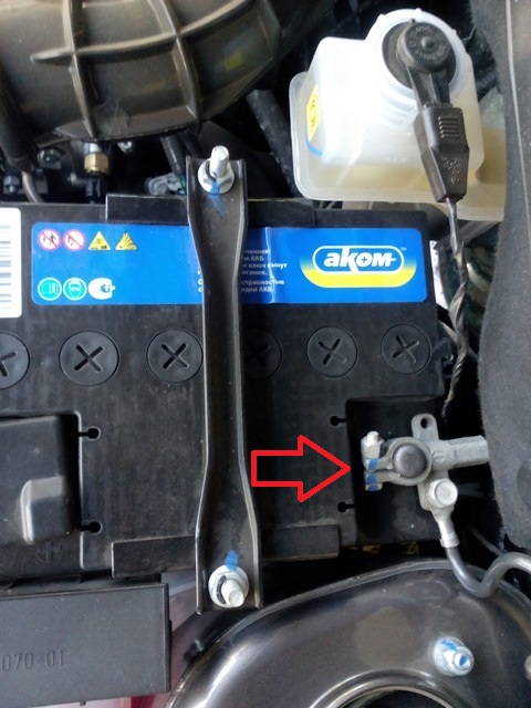
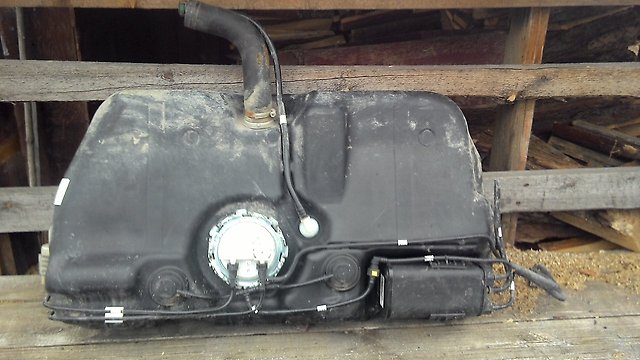
1. Relieve pressure in the supply system .
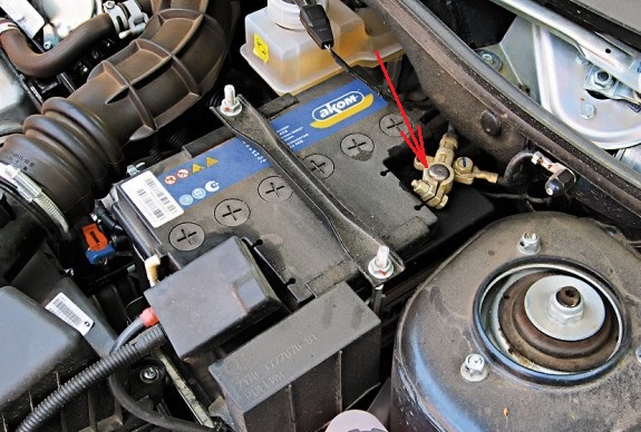
2. Disconnect the wire terminal from the negative battery terminal.
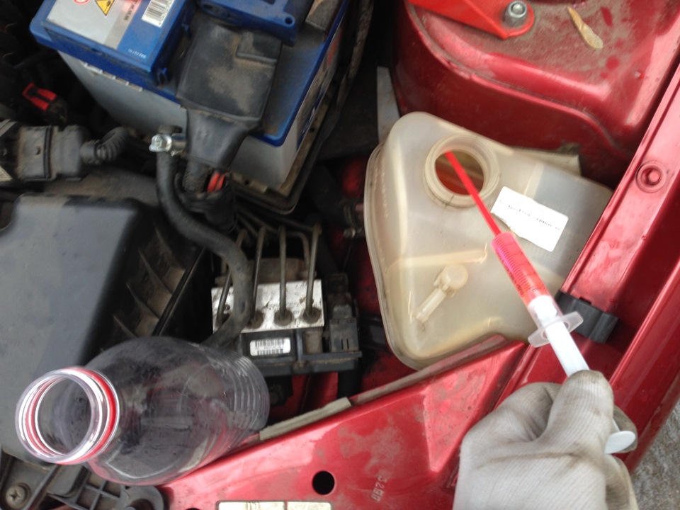
3. Drain engine oil and coolant (see here for 8-valve engines or here for 16-valve engines).
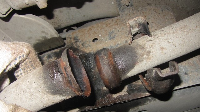
4. Disconnect the additional muffler pipe from the collector as described here .
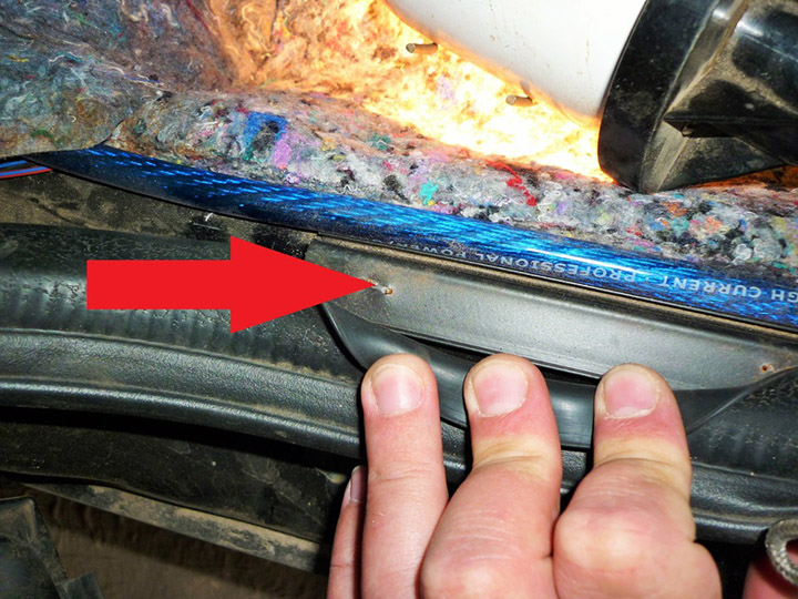
5. Disconnect the fuel supply hose tip from the fuel rail tube as described here (for 8-valve engines) or here (for 16-valve engines).
6. Remove the air filter and air supply hose to the throttle assembly .
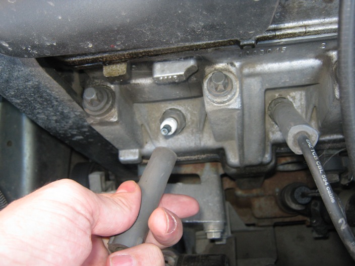
7. Disconnect the vacuum brake booster hose and the tip of the canister purge solenoid valve tube from the receiver fittings, as described in this article .
8. Disconnect the engine management harness connector from the engine coolant temperature sensor connector as described in this article .
9. Disconnect the cooling system hoses from the cover and thermostat housing, and also disconnect the “ground” wire tip from the cylinder head stud, as described in this article .
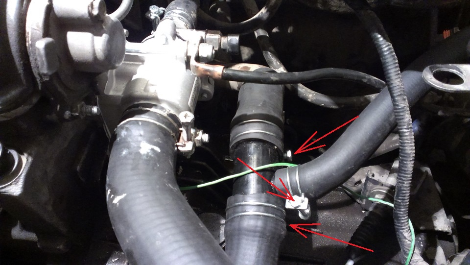
10. Using an 8 mm head, loosen the clamps that secure the three hoses of the cooling system to the nozzles of the pump inlet pipe and remove the hoses from the pipe nozzles.
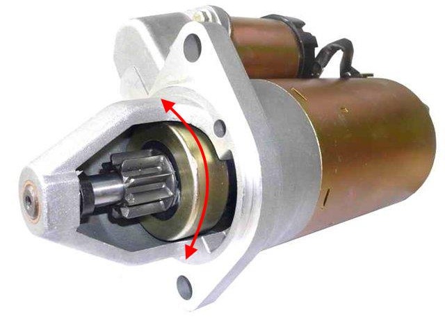
11. Remove the generator .
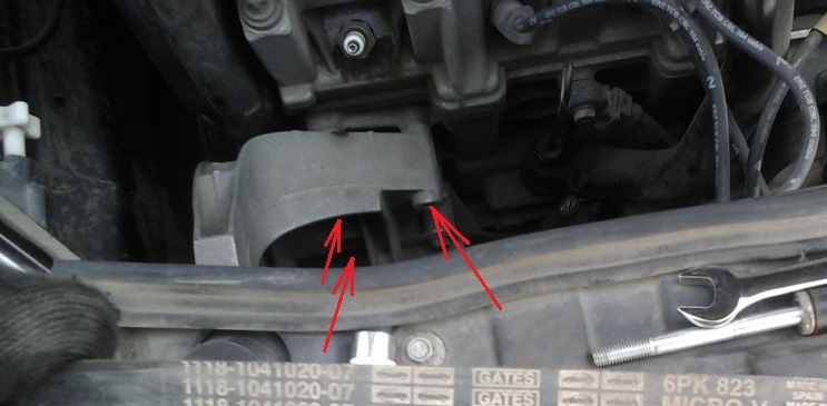
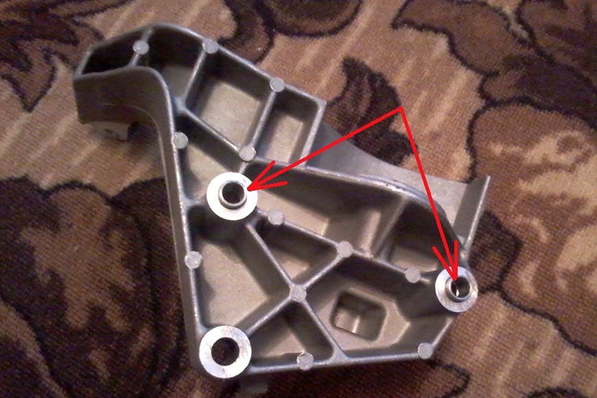
12. With a 13 mm head, unscrew the three bolts securing the generator bracket and remove the bracket (the mounting sleeves are located in two holes).
13. Disconnect the engine management harness connectors from: fuel injector harness connectors (see here for 8-valve engines and here for 16-valve engines) and oxygen concentration sensors: control and diagnostic .
14. Disconnect the engine control harness connectors from the connectors: throttle assembly control unit , ignition coil (see here for 8-valve engines and here for 16-valve engines), crankshaft position sensor , knock sensor , insufficient signaling device oil pressure , canister purge valve , vehicle speed sensor .
15. Take away plaits of wires from the engine aside. Remove a transmission and coupling .
16. Place a soft material on the bottom of the windshield (you can use a cloth folded several times). Raise the hood to a vertical position so that its rear edge rests on the fabric under the windshield.
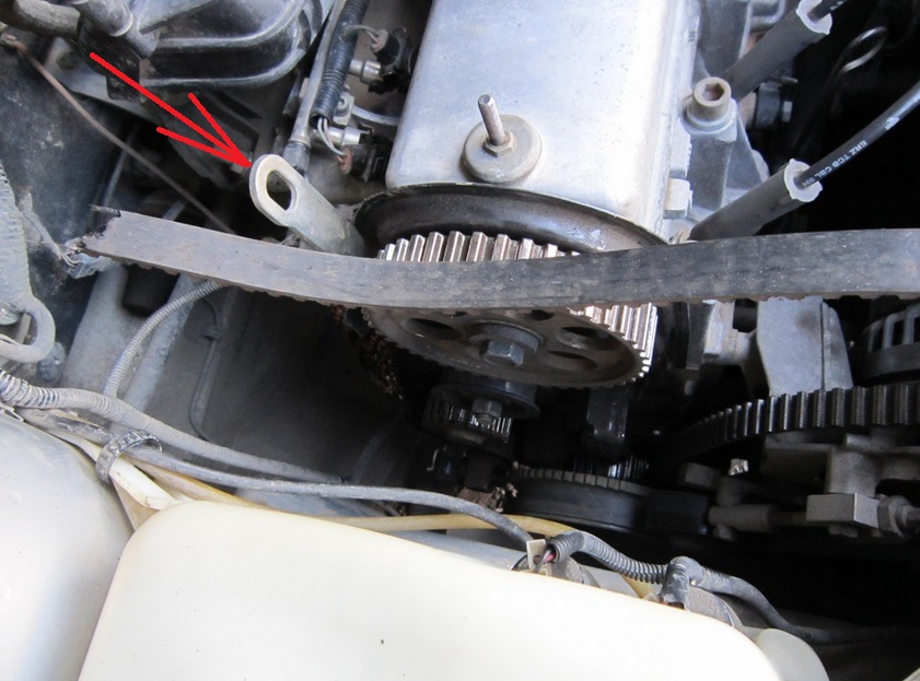
17. Fasten the chains of the lifting device on the engine on the right side for the regular eye 1, and on the left side - for the bolt screwed into the hole in the cylinder block, designed for fastening the clutch housing.
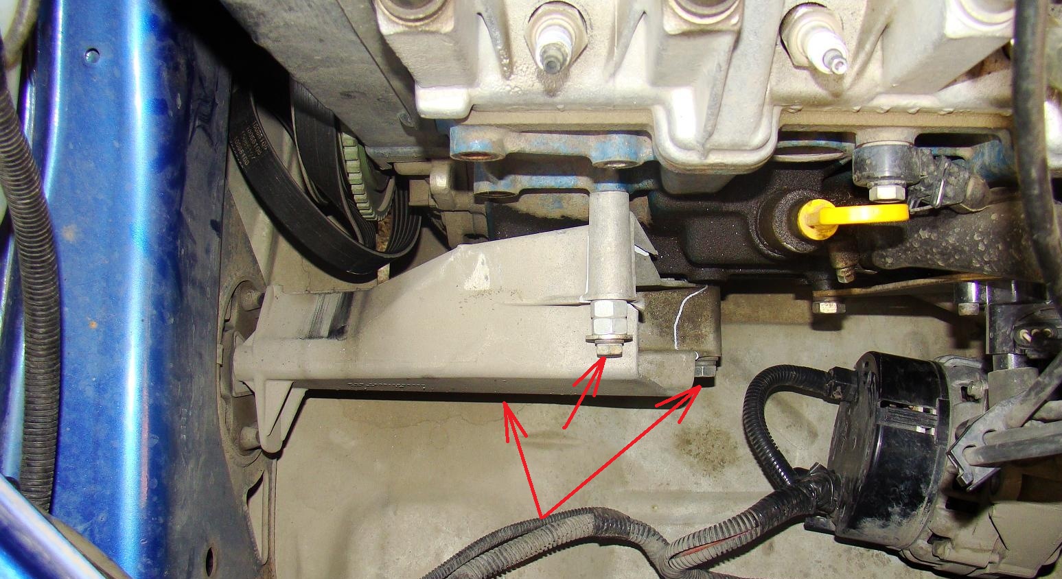
18. After tightening the chains, remove the stop from under the engine that supported the engine when the gearbox was removed. While holding the engine, unscrew the three bolts securing the bracket of the right support of the power unit to the cylinder block: with a 13 mm head - the upper mounting bolt and a 15 mm head - two bolts of the lower bracket mounting (one bolt is not visible in the photo).
Note:
Before removing the engine, it is necessary to check whether all hoses, tubes and wires are disconnected from the engine and laid aside.
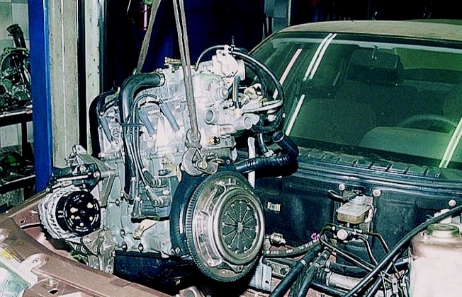
19. Raise the engine with a lifting device and remove it from the engine compartment.
20. Install the engine on the car in reverse order.
The article is missing:
- Tool photo
- Photo of parts and consumables
Source: carpedia.club